
Space 1999 44" Eagle Transporter
1/24th, Studio Or Thereabouts Scale


 Page Number
Some framing fiddling about
And A Few Other Bits Besides.
Welcome back all!
Right, spine framework time so let's get to it.
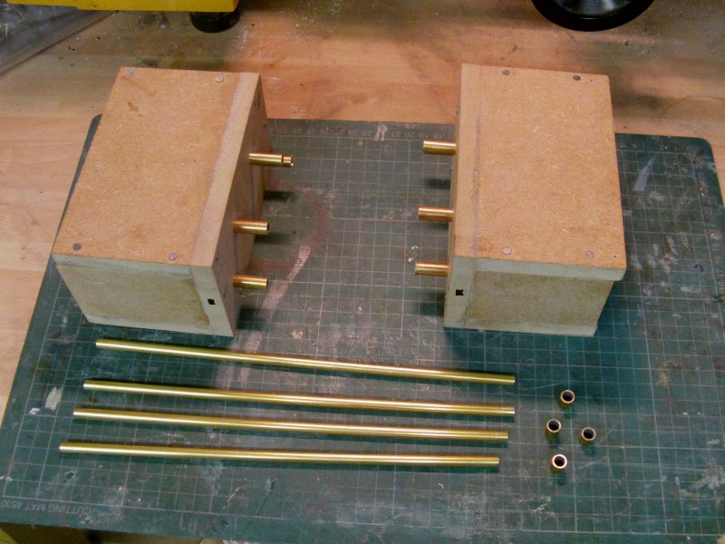
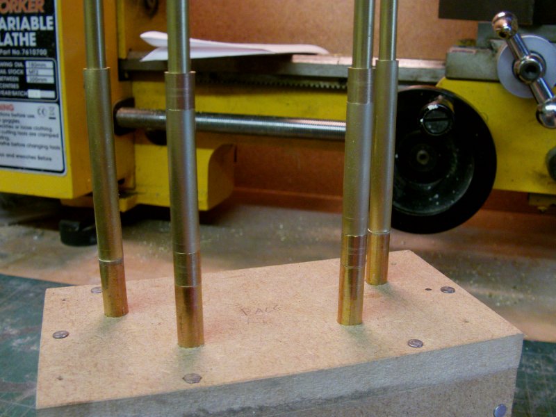
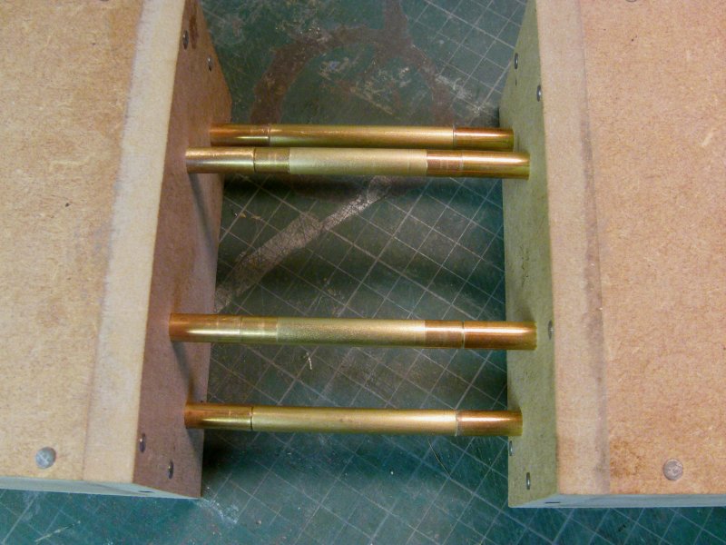
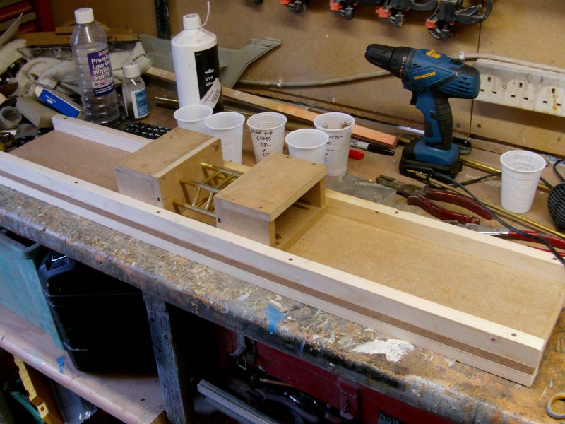
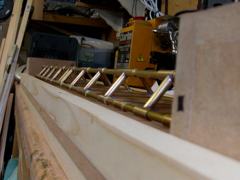
So fist things first, a jig of sorts.
12mm MDF, mucho measuring, sawing up a plenty, holes drilled, glue, nails, resin and brass pipe...
Get's this...
The resin I spoke of is epoxy poured in to the blocks about 15mm or so,
to seal and hold the brass tube in place.
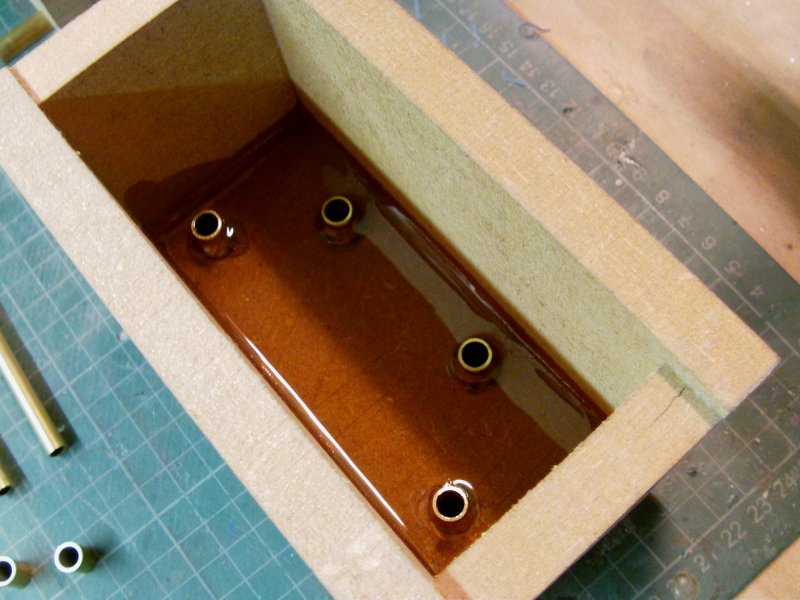
They are not going anywhere!
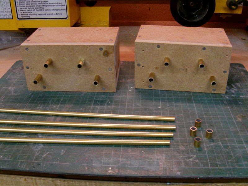
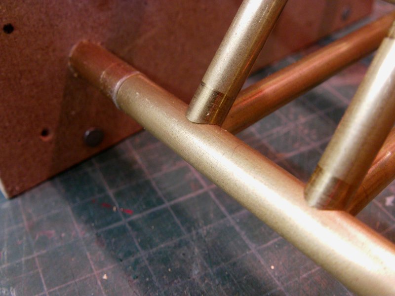
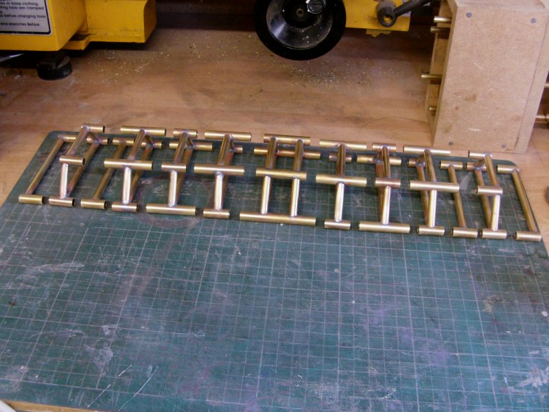
Four lengths of 6mm brass tube so the trapezoid shape spine formers can be built first.
Nine of those type and four single bar ones required.
The tube used here is almost true 6mm diameter so the spine collars will slide easily over.
That 6mm was a bit of a sod to find but got some in the end.
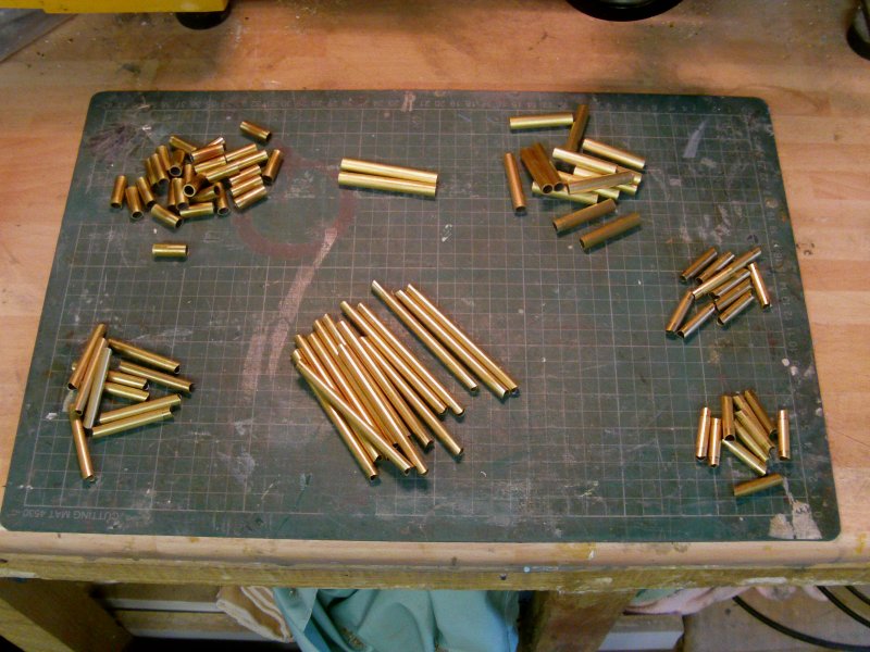
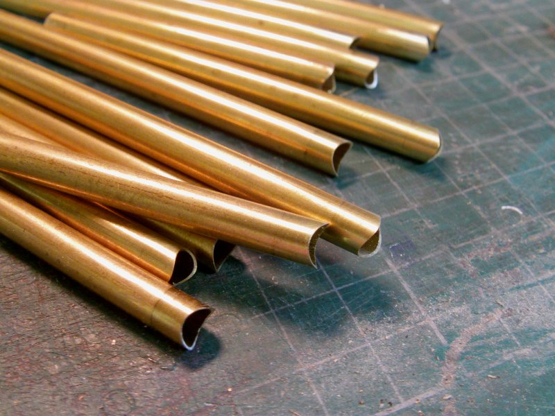
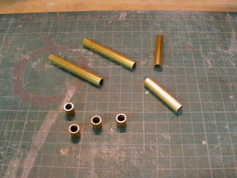
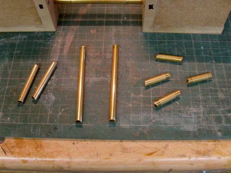
The relevant diameter brass tube already sliced and machined for the uses.
This lot...
The collars which will go on the longerons for the spine are 5/16th inch diameter 20 SWG wall.
The studio models have the thick walled stuff like that for the spine collars so good enough for me.
Couldn't for the life of me find a thick walled metric equivalent in this country so had to go for
imperial dimension stuff and then find some 6mm or close to fit through it.
The stuff for the cross pieces and angle sides is the bog standard 0.35mm wall 6mm tube.
Well it's listed as 6mm but more about 6.35mm or 1/4 inch in real money.
in order below, the top cross, sides and bottom cross parts.
Now all those collars were cut at 20mm x 28 of, 40mm x 14 of and 60mm x 2 of.
First up are the collars for the center former of the spine.
2 x 40mm, 2 x 60m and 4 x 10mm spacers.
Slid on to the jig like so.
Then the other block slid on the 6mm tubes and pushed together.
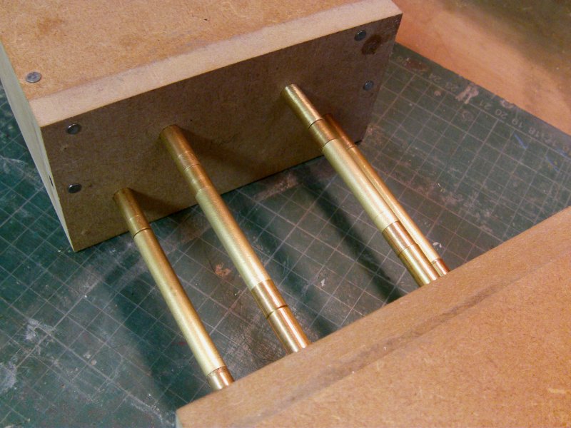
So the top/bottom cross pieces and sides pulled out and slipped on the jig.
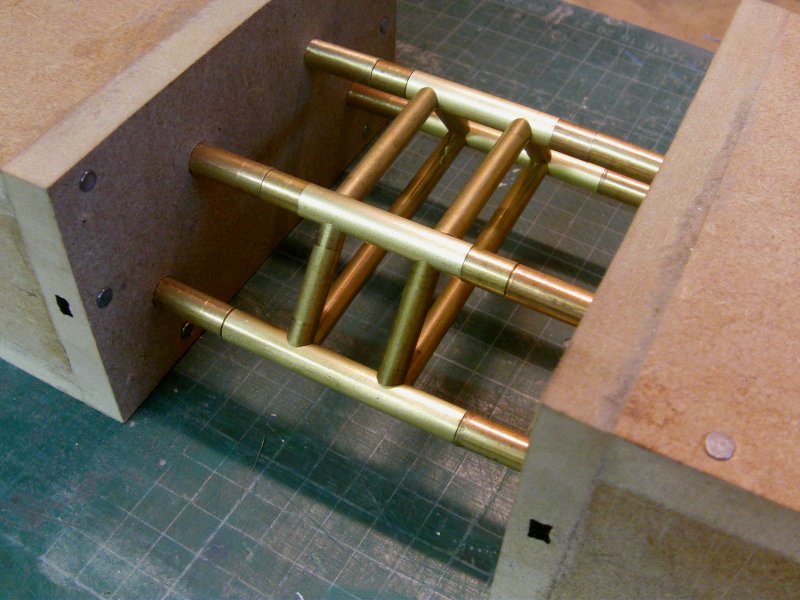
Now the important thing here is snug fit all round.
This makes it stronger and makes soldering a lot easier all round.
So to really make sure it's all kept lined up, a base plate to slip the blocks in to and will also stand in
when the spine is built proper.
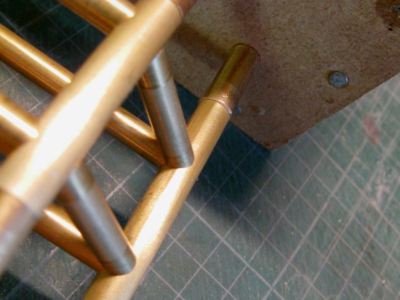
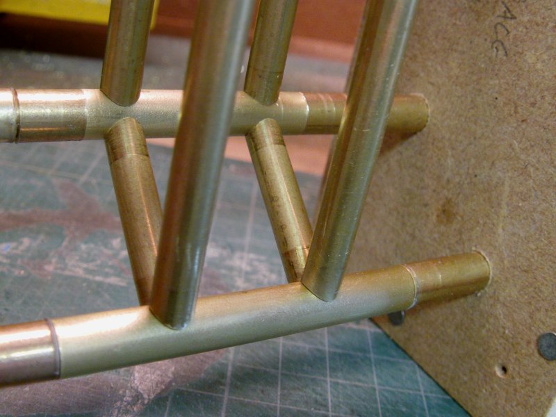
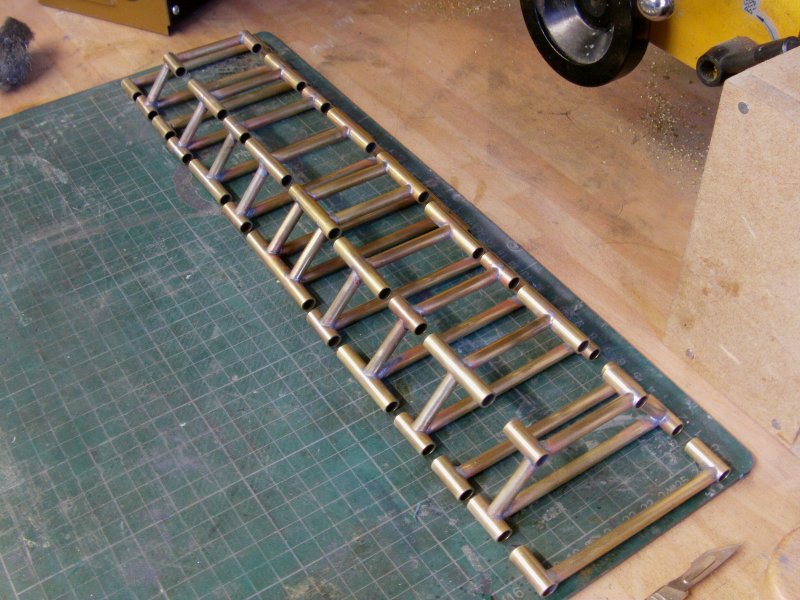
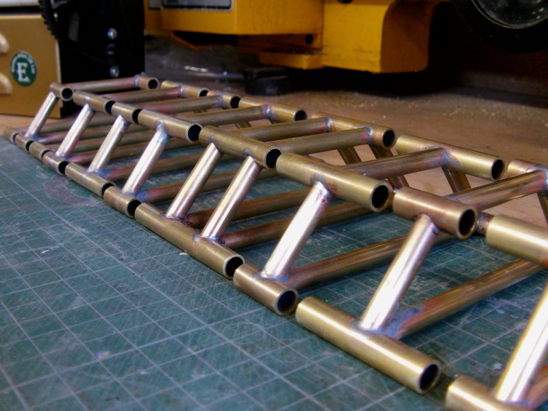
So as per the cages, the same soldering routine.
Lightly on the flux paste and very small amounts of solder.
The snug joints don't need that much and it will make eventual pre-painting cleanup easier.
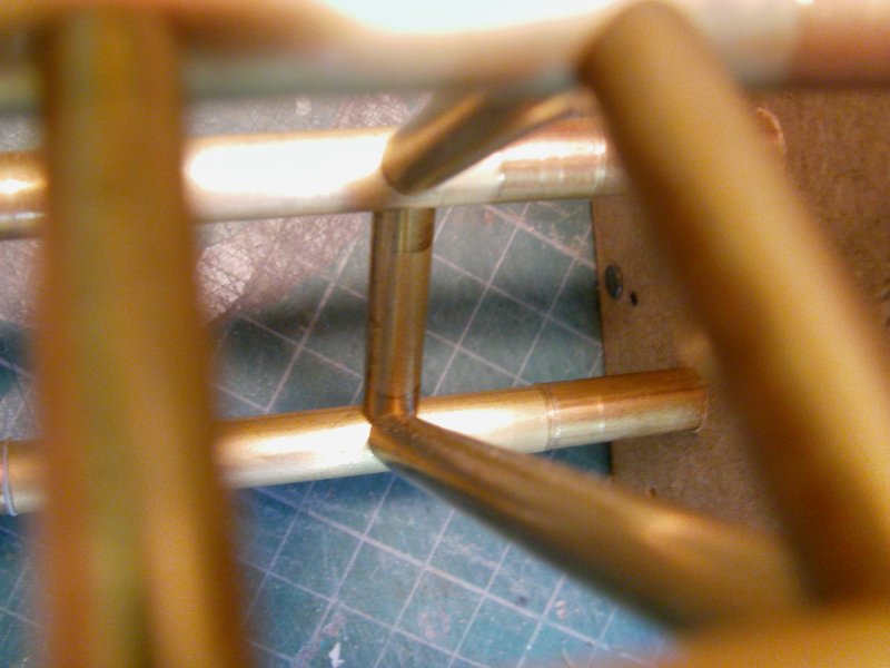
And much soldering was done.
The parts below have had nothing more than a quick rubdown with some mid grade steel wool.
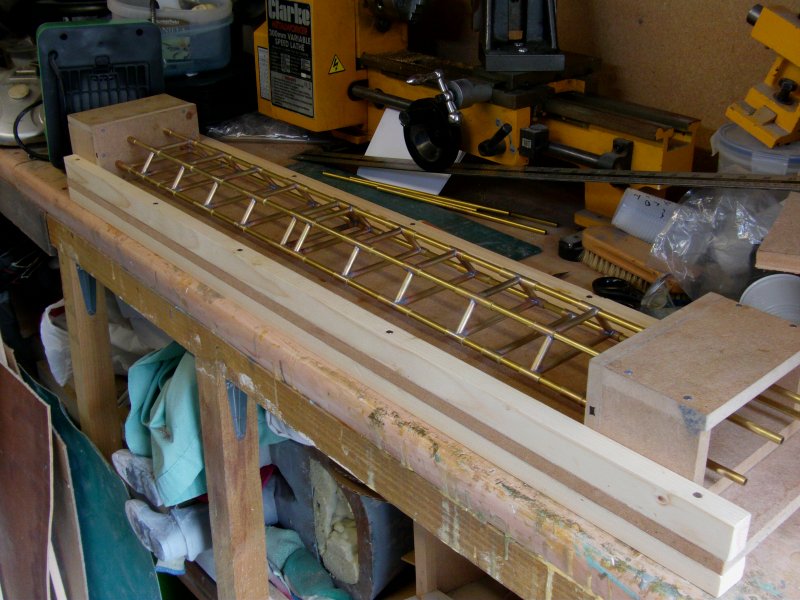
And as a rough line up, in the jig with the 6mm tube longerons.
Said longerons are .50mm thick wall tube.
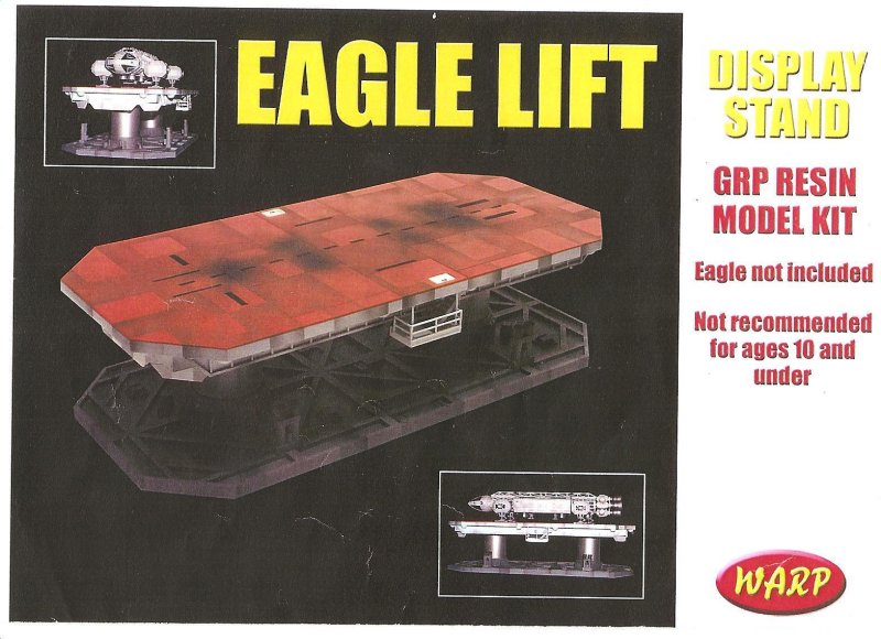
OK, as a last thing for this update, the client has specified what he would like for a display stand.
Now something like the Warp kit of an Eagle lift has been requested.
Kit box front looks like this...
The client sent me a pic he found on the web, an entry by some talented soul from the 2017 Wonderfest methinks
but it shows what one of these beasties with an Eagle on looks like.
And it's a bloody nice build I must say.
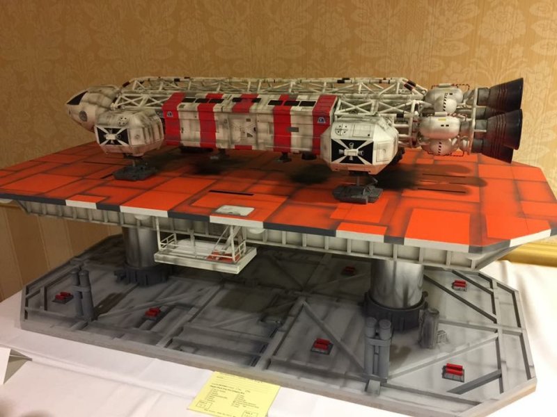
Now that said, the Warp one is for a small 1/72nd Eagle...
this one is a bit bigger so out with the paper, pencil and stick of inches.
Had to tape together twenty bits of A4 paper to do it
as I didn't have a single sheet big enough on hand.
Just a rough plan for me to get a grip of the size and basic layout...it ain't no tiddler.
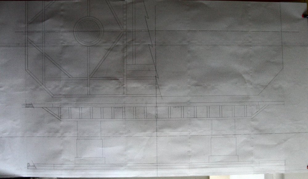
Overall, the final thing will be 48" long, 24" wide and 12" high,
Eagle not included but that will put about 7 or 8" or so on top at a guess.
So details and some sizes might or will change as we go along with the display base and it will
certainly get the serious detail treatment as one reckons it will need it at this size.
Lighting for the base to illuminate the Eagle will be included of course.
Next update, nuclear waste pod and moonbuggy buggering about will be going on!
See you merry mob then, go easy out there all of you.
Page Number