
Airfix DeHavilland Mosquito
1/24th Scale


 Page Number
Just a few things to be dealt with...
And Maybe A Foretelling Of Problems To Come.
Whatcha gang!
Well back again with just this quick bit of update uproar in between Dropship paint dabbing.
Now as noted in the first page this is a heck of a kit but not for the faint of heart.
And now here's a small expansion on that.
Not to say that it's beyond anyone's skills to tackle but here's the thing.
The problem with the complexity of some of the parts is the ejector pin/moulding disc marks in the parts.
Granted that generally this is an accepted thing on injection plastic kits but on this beastie...
Well they are going to cause grief and there's no two ways about that.
Upgrade that to severe grief if your planning on doing the fully detailed, panels off, showing all the nuts and bolts deal.
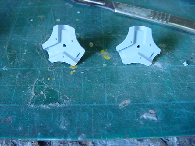
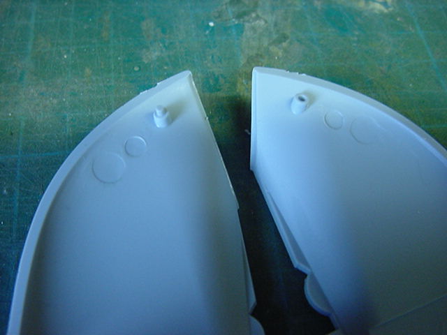
So as a pick of the examples, here's the crew access door.
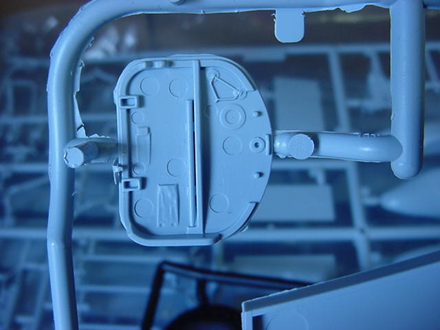
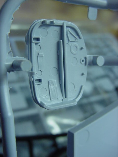
I think you can see what I mean.
Granted the Mossie has all manner of lumps and bumps inside but not quite to this extent.
Here's one of the bomb/gun bay door parts and the inside of one of the bomb bay parts.
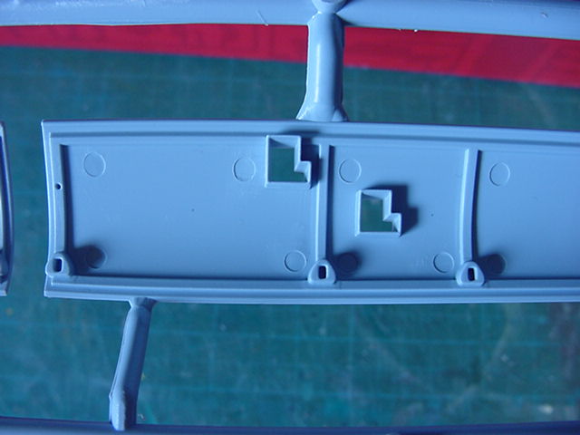
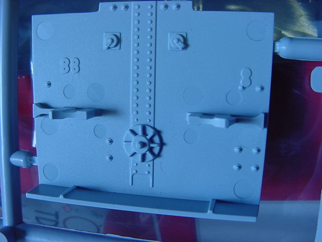
At the most, I would say the pin marks are some 2 to 3thou" deep.
And yes, they are a pretty widespread thing on a lot of the parts.
One may decide on how bad that is but if my recommendations stand for anything with you merry mob out there, it's this:
If your prepared to go through what will be no easy thing sorting it out then this kit is for you Mossie fans out there.
Then again if you're not bothered by such things then by all means pony up the folding stuff and have fun building this beauty.
If however, it's something that you may think is beyond your capacity or patience to tolerate build wise then keep ya money where it is.
I know that sounds blunt but no pint in being disappointed with something you have paid no small amount for let's be honest.
Granted i'll reckon we have all been through the fill in/clean up the moulds disc thing but everyone's got their limits.
Unless of course you're loony, masochistic and/or bloody minded enough to plod on anyway.
Which pretty much covers my attitude to this modeling lark on all counts.
Well all that said, time to have a fiddle about.
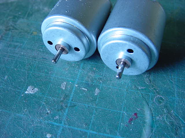
The electric motors arrived this day, overnight shipping a bonus to me when ya local supplier is out of them.
So here be they with the prop hub parts hacked from their sprues.

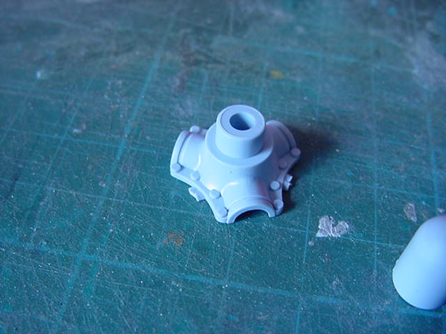
Nice parts and fit together okedoke.
One small issue, this part...
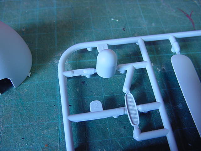
Which goes on the prop hub and connects to the spinner.
Looking through the plans, well maybe it's just me but there no mention of it.
Yes it's there and pics in the destruction manual show it in position but no mention before hand of when and how it goes on.
For most it's not a problem I am sure but it still may trip some up so I just thought it worth a mention.
No idea if there are any more instructional errors but if any crop up, i'll let ya know.
So first up after a trim and scrub down for the parts is the fitting t the motor shaft.
The motors I got, the equivalent pretty much to a mabuchi R-260 type, 3v whizzy things.
They'll do.
The shaft is about 2.2mm diameter or just shy of 3/16" in real money.
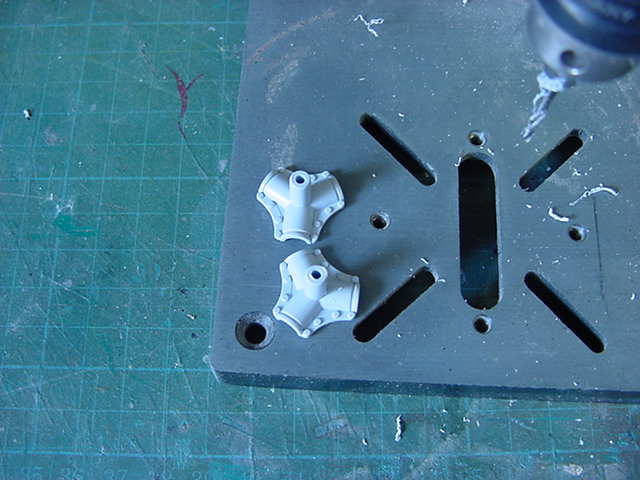
The prop hub has a small hole in the back of about 1mm (1/16") so widening time.
Mini drill in stand and three drill bits.
Working from a bit larger than the hole already there up to the size required.
Slow and easy does it and sorted.
The hole does not go all the way through originally but it does now and this will certainly help when the gluing thing happens.
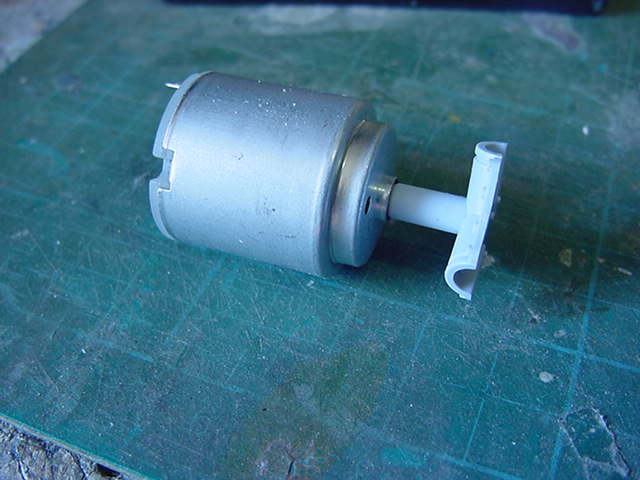
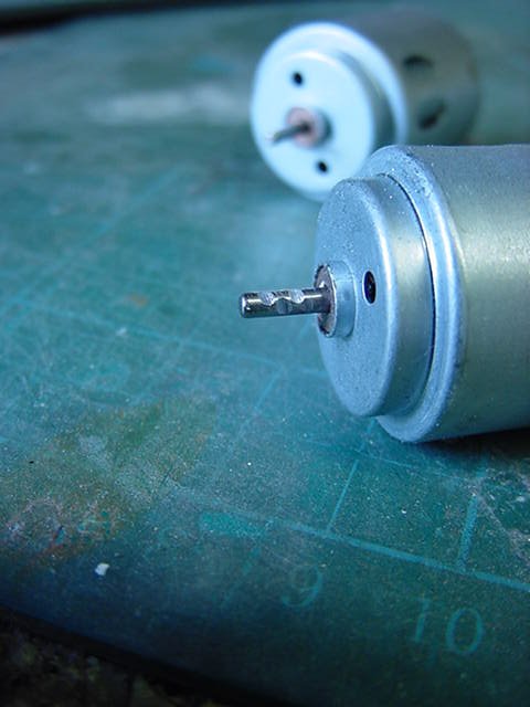
Also the motor shafts had a little touch here and there with a cutoff wheel in the mini drill.
Just to slightly notch them to give the eventual adhesive something to get a grip of rather than just smooth metal alone.
A bit of gluing action later and they were all together.
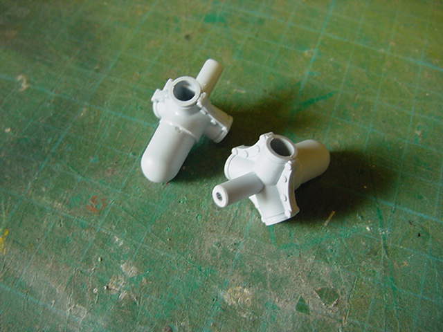
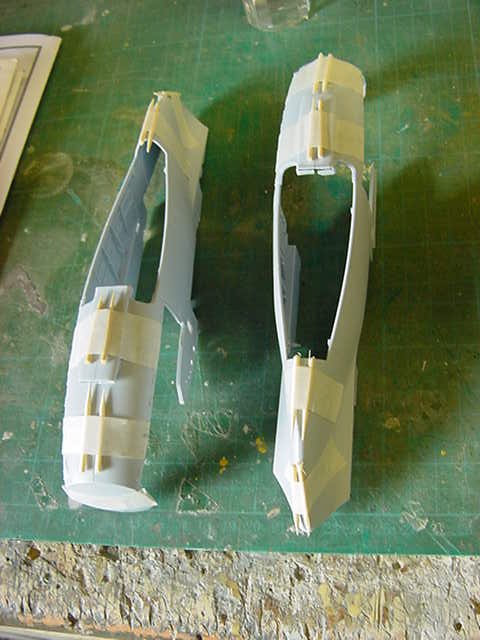
So then, the engine nacelle parts located and a pair of side cutters waved at 'em.
After a trim up and test fit, something to note.
The locating pin and hole at the rear...this bit...
This is a tight fit almost in the snap together category.
It takes a bit of pressure to drive it home and once done it won't come apart in a hurry.
So don't force it untill your ready with the sticking it together proper stuff.
Also of note, the locating pins/holes are only on the very rear and at the very front of the nacelles.
I would say this is to make the fitting of the engines easier but careful alignment and gluing is required where it has the underside air intake scoop thingy.
Other than that, no dramas in putting the sides of the nacelles together.
Now some may well ask, what's with the toothpicks under the tape?
Good question and the answer is this:
I don't know about the glue you use but if ya use the hot stuff, Tenax, MEK (my usual choice) or the like, you know it goes everywhere along the join.
As indeed it's supposed to and fair enough.
Well if your using tape to secure something, sometimes the glue goes straight through the join and spreads under the tape.
Nasty glue burn, tape residue and a defect in the surface to sort.
Well not a fan those things I so here's a tip for what it's worth.
Toothpicks or cocktail sticks, either will work,
Placed under the tape strip either side of a seam before applying glue to the joint means the the tape does the holding together,
but it keeps it off the seam.
A bit like this...
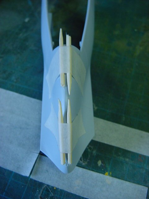
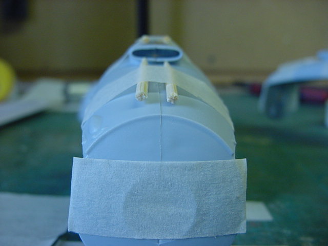
Nicely held seam while curing, no glue burn, sorted!
Well sides of the nacelles to add then the bracket work to hold the motors...
And so on...
That's for next time so you lot go easy now and i'll see thee later gang!
Page Number