
Salzo Battlestar Galactica
TOS Viper Fighter.
1/12th Scale 31" long


 Page Number
A mere question of piping...
So Let's Pipe It Aboard!...
Along With The Other Stuff.
Greetings gang!
Welcome back to a hellhole twofer special.
Double update, the end of which will see the launch tube a done thing.
Then on to the rest of the ridiculousness but that's for later.
So then, last time as you may or may not recall
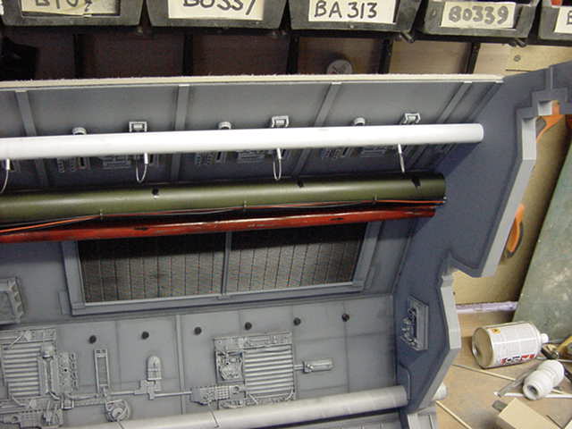
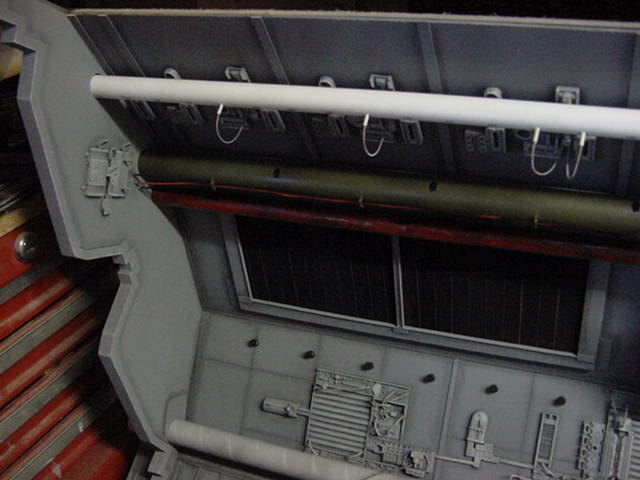
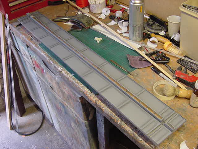
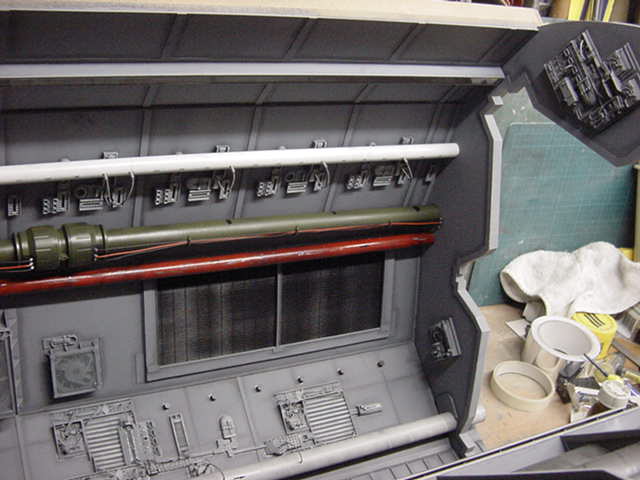
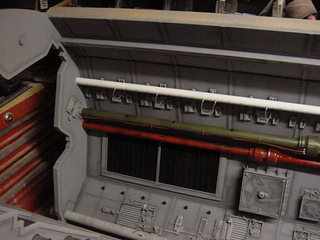
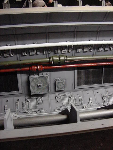
a bit o' piping and two more wall plates to get sorted.
Second to last panel got the fast becoming standard build/greeblie/paint/shade samba around the hellhole
and was introduced to the epoxy stay put gunk and four small screws.
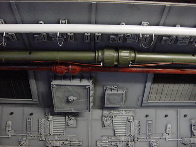
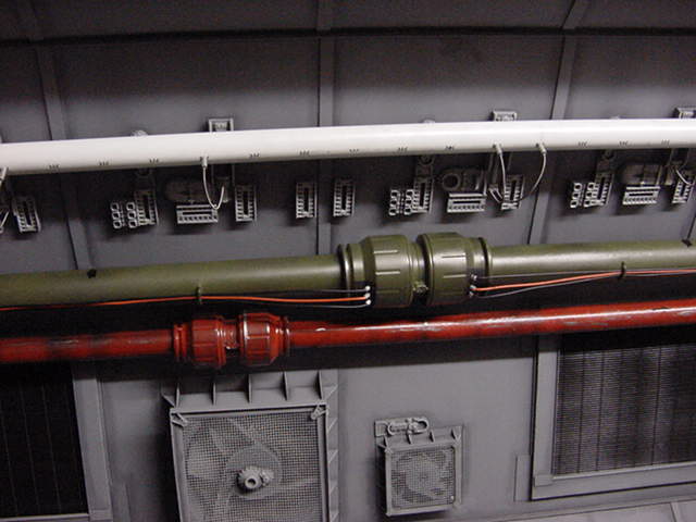
the penultimate 15mm pipe got the paint and fit routine.
Ably assisted looks wise by a push in connector and a dollop of red paint.
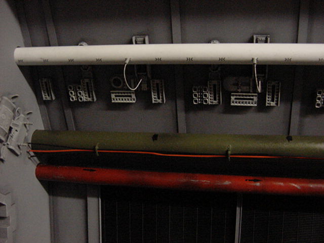
Once all settled and some rubdown black arrows applied
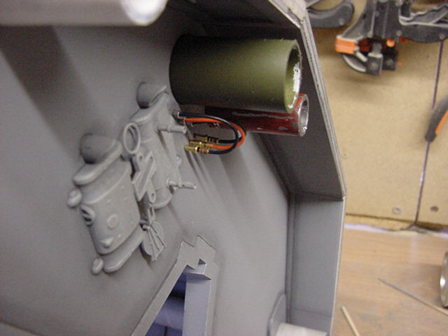
then came the last of the 22mm pipe.
A push in pipe connector, some wires and assorted bits got lobbed at it
after some olive drab green paint had got told where to go.
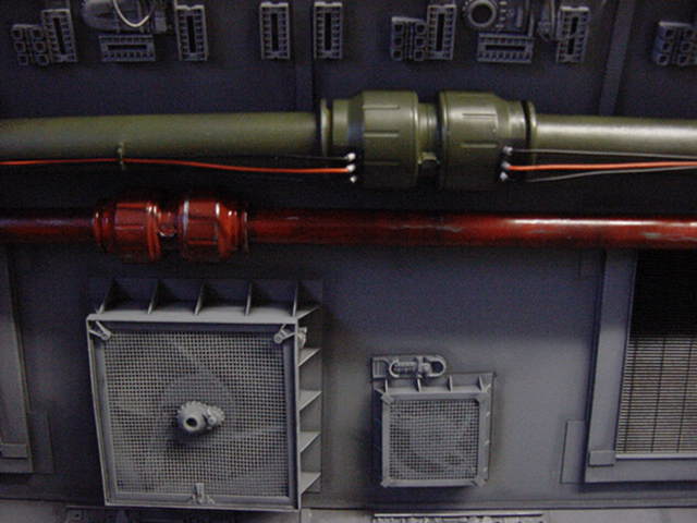
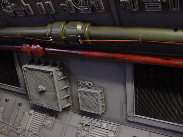
Then came the last bit of 15mm pipe to be added.
Only mildly messed about with and fitted up a treat.
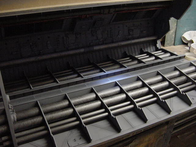
So that little task accomplished, last of the panels.
The top one contains the lighting gear for this beast.
Built more or less in the same fashion.
6mm MDF, 2mm acrylic clad etc yaddayaddandsoon...
Well here it be.
Enclosed in the middle bit are 33 LED's.
5mm 12000mcd white jobs, spaced out at an inch and a smidgen a piece.
30 make up the main run, the other three are set in the center.
Like this.
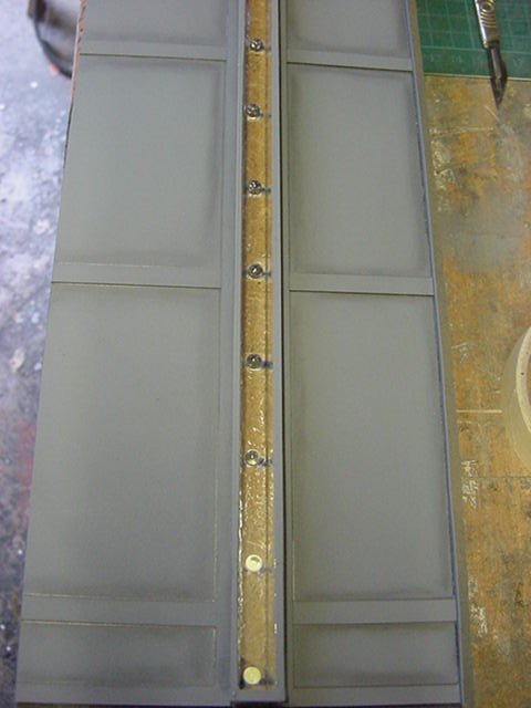
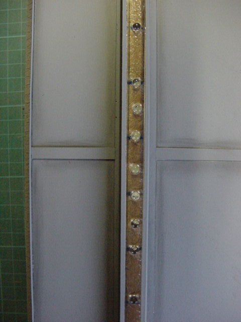
The three in the center will be tied in to the constant on circuit,
the rest are linked in groups of three to a chaser circuit.
the circuit was found online at THIS HERE WEB PAGE.
I've found that sometimes that page doesn't come up so just incase, here's the graphic showing the chaser circuit from that page.
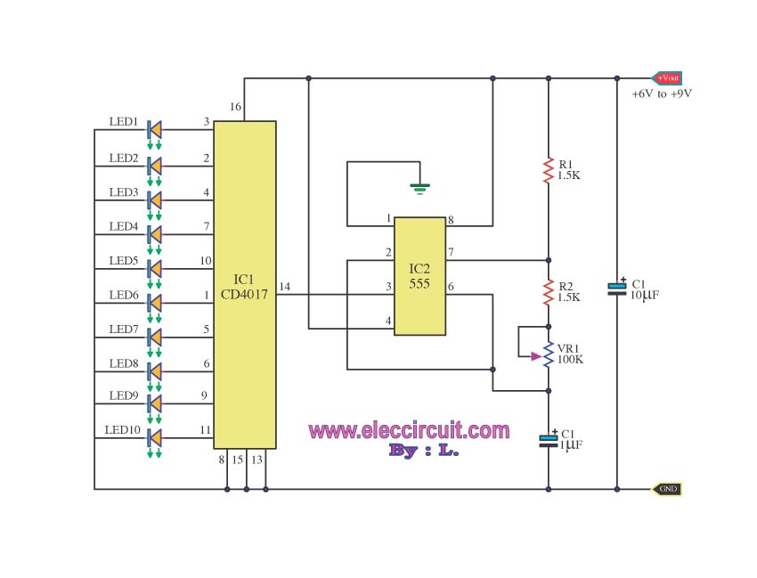
Simple and straightforward enough for even me to wrap my brain around and it works a treat.
A variable resistor is in the circuit so that gives you adjustable speed
on the chaser effect so it's all good and runs for a looooooooooooooong time on a 9v battery.
I let it run for about 12 hrs continuous before I decided that was enough,
it had proven itself and all the LEDs were still working so okedoke!
So that plate got fitted in position.
As it happens, when the Viper is placed in the tube
that constant light spot falls right on the cockpit area.
So the the final lighting bit in the tube.
Yes, there will be a video of the lighting in action
at the end of the next page so fret thee not.
NO DON'T GO RUNNING OFF THERE YET!!
Easy does it my friends, take ye some time my impatient ones.
So the next and final bit for this page, the lighting bit.
Now there are areas that will be fitted with LED's for the 'mood lighting' part of this debacle.
Those places as indicated by red circles in the following pics...
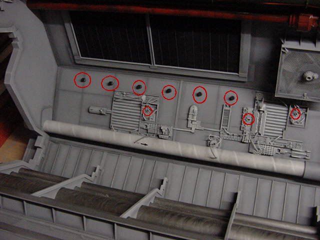
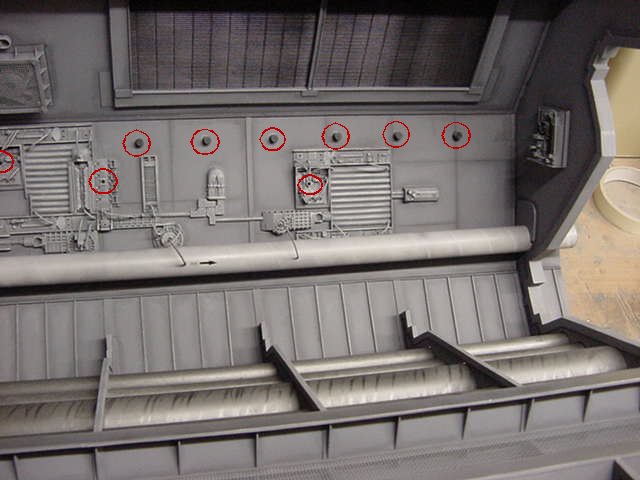
So all well and good, no problem in fitting them.
The wiring up is another matter.
Simply put it comes down to two choices:
First, run the wires up the outside of the rear wall.
Pros, quick and easily done.
Cons, unless covered by some means or channeled in to the rear timber (which would weaken it)
they could be easily damaged.
Not a good idea and covering them means adding more weight.
Once the Viper is done and in there.
i'd estimate the all up weight to be somewhere between 30 to 40 lbs.
Or bloody heavy if you will and after lifting it a few times as I have,
That migrates from
'This thing is a bit lumpy'
to
'Actually it's getting a bit bloody heavy!'
to
'There goes me back...again'
In a fairly short space of time.
Second choice, run the wires through holes in to the launch tube itself and make them part of the show.
Pros, will add a bit extra to the look of it.
The wiring will be safe from harm.
Cons, it'll take a bit longer but not much.
Just a bit extra work.
I can live with option two so off we go!
So then, the wires have to have something to run through so some form
of bracketing/support would be nice idea here methinks.
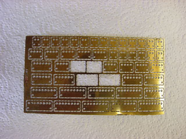
A little while hunched over a warm PC gave me this...
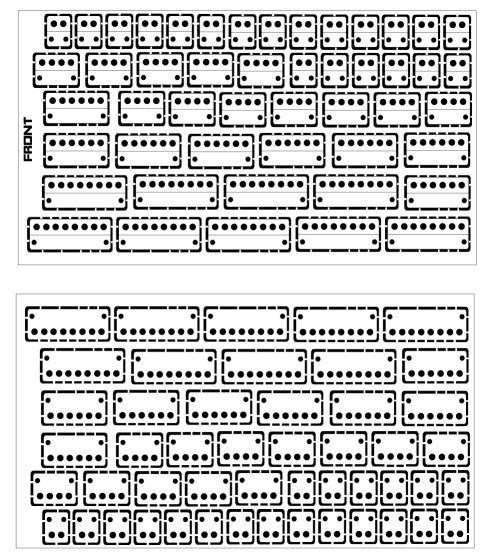
That pic is about 20 times smaller in resolution than the original.
This became the pattern for some photo-etch frippery.
So after a bit of UV light messing about,
a small lump of 10thou thick brass brought in to play,
some rather dodgy and major league corrosive chemicals heated up,
50 degrees C for that special down home hellhole flavour with just a hint of rotten eggs,
poured in to the etching tank and aerated the living daylights out of the brass sheet.
A swift bath in a pot of caustic solution and a brisk rubdown followed.
The brass, not the builder I hasten to add.
After which we got this.
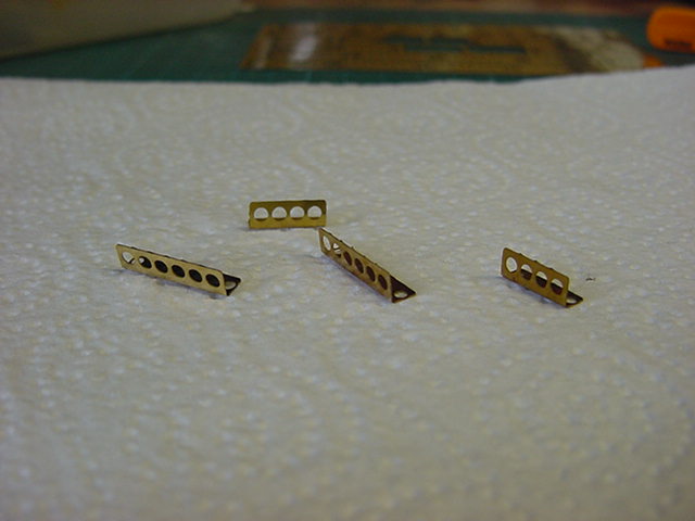
The four in the center of the plate fell out during
final scrubbing down so not lost I am happy to say.
So said four were given a quick test fold
to see how it was all working out.
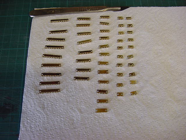
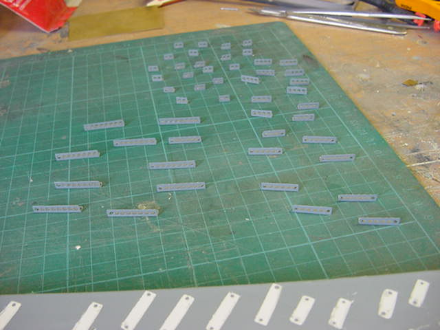
Looks good so all of 'em were cut from the fret, trimmed up and folded.
Took a while.
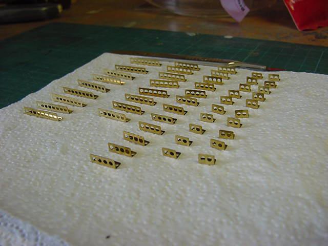
None too shabby.
A scrap lump of MDF with some double sided tape attached,
all bits stuck on and the grey primer got thrown in their general direction.
And away to the thirteenth page of pandemonium with you and i'll see ya there!
Page Number