
Battlestar Galactica Viper MkII
1/10th Scale.


 Page Number
Bits going round and round...
And More Lumps Getting Chopped Off.
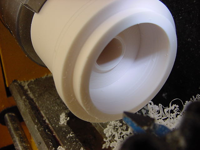
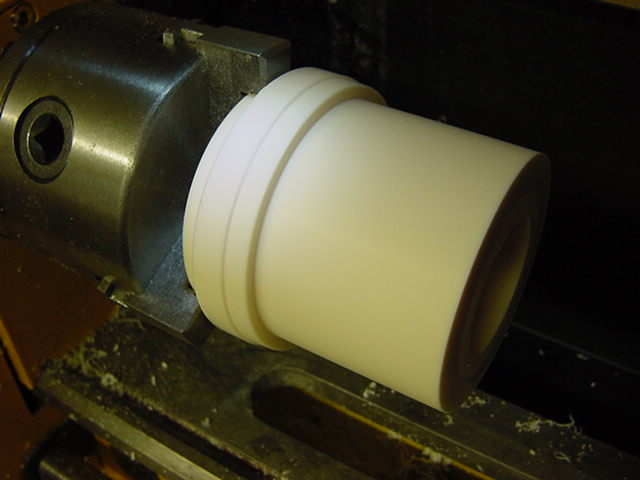
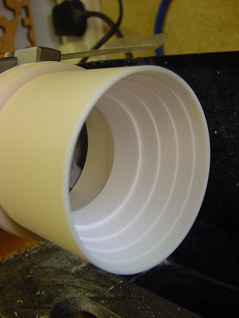
Ah, there ya be, right then.
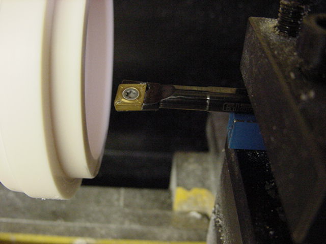
So last time, shoving a sharp implement into resin.
A short while and much frag falling out later...
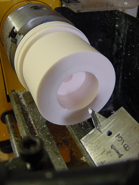
Sorted this end, now for the other.
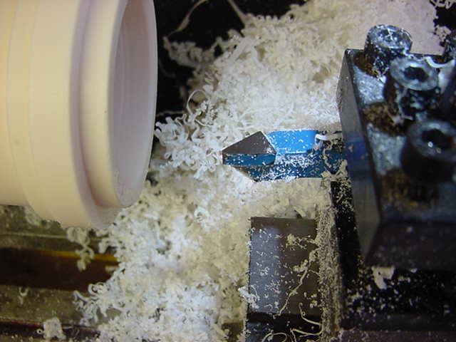
Just incase you were wondering,
I couldn't go all the way through as the point would run into
the turning lathe chuck long before I got through it.
Which would have resulted in some expensive noises occurring I'm sure.
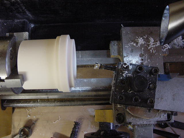
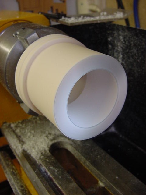
So then, time to fit the open jaw set for the turning out of the back of the can.
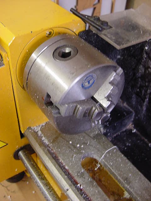
Resin lump about faced and fixed in.
After a rotation check to make sure it was running true,
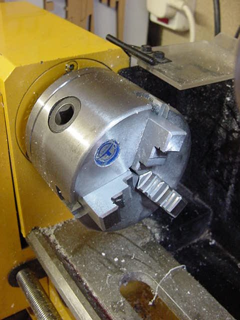
time to get the rest of the unwanted stuff gone.
Spade bit done it's work then in with the internal diameter rough turning tool.
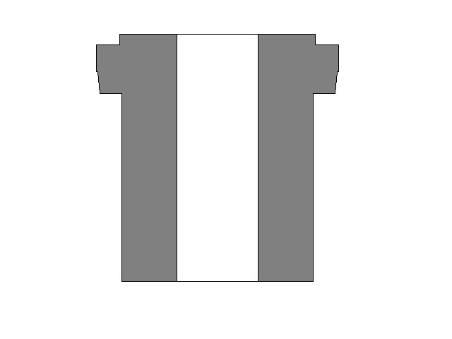
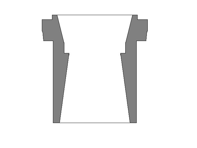
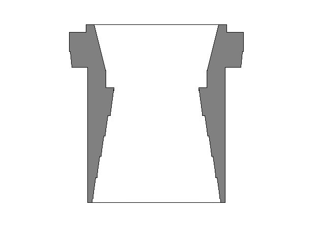
Now what we have essentially is something like this:
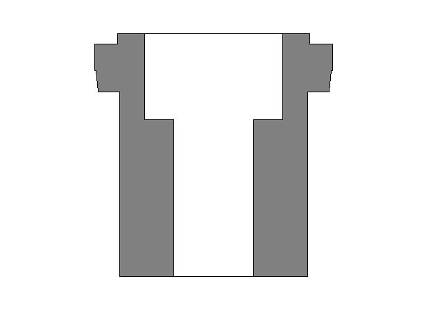
Going to this:
Next up, set the tool post on a 10 degree taper, switch tools and cut.
So what we have is something resembling this:
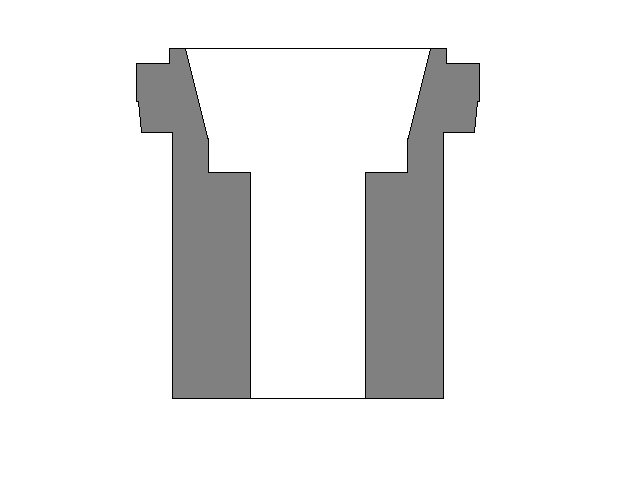
Now the reason for the taper in is that as we go along,
i'll make up a cast resin cup that will hold any lighting set-up
required and slip snugly into place on the shoulder.
The taper is there so it will make it easier to remove when doing the dry fit testing.
And pretty much self-centering when the assembly happens proper.
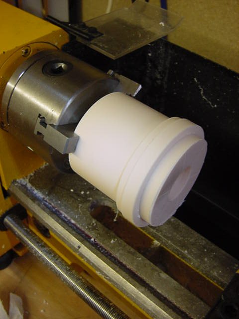
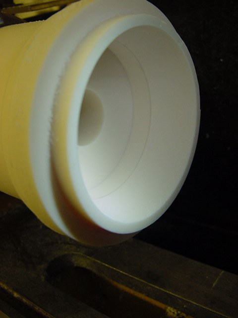
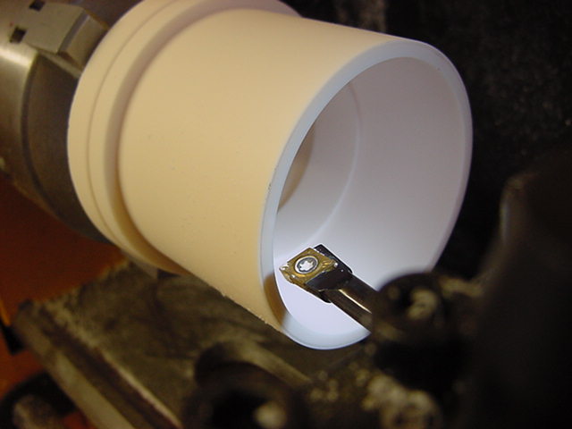
So that end done and dusted, time to turn it 180 about and get the rest sorted out.
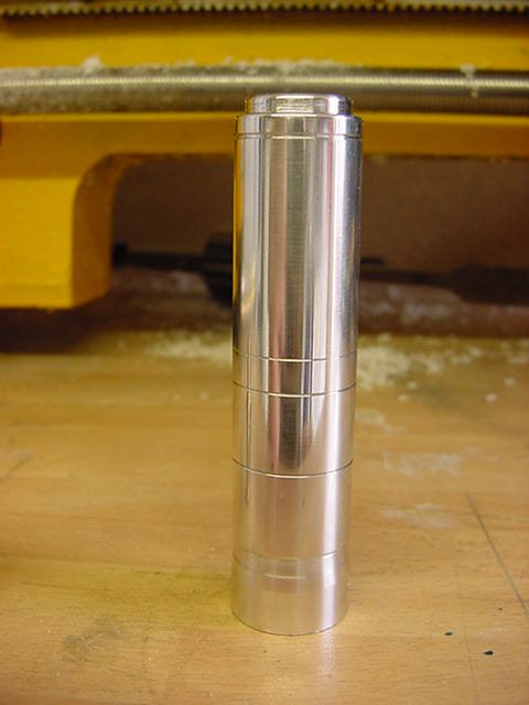
Once set in and ready, all outer surfaces were faced up to their proper diameters.
So inside material removal.
Tool post set back to center, internal diameter tool fixed in and much back and forth on the slides.
So roughed out proper, then the tool post set to a eight degrees and the internal taper cut in.
From this, the stepping as seen on the CGI model and full size studio piece was cut in.
Using the same taper and divisional marking.
The inner final ring was cut.
Then the tool stepped out for the next ring and so on.
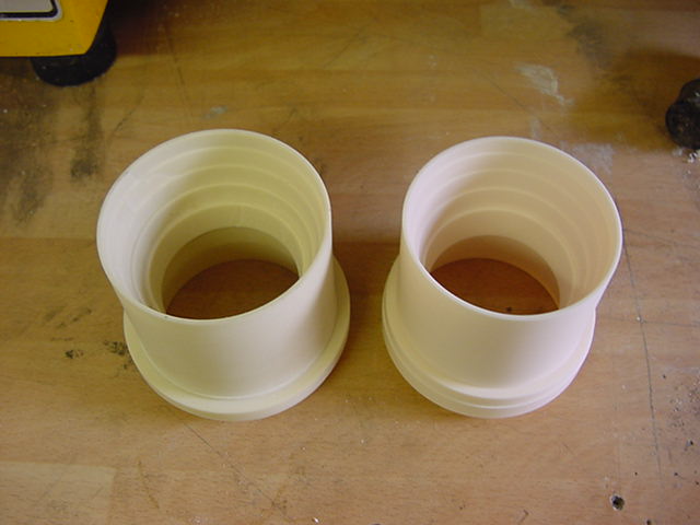
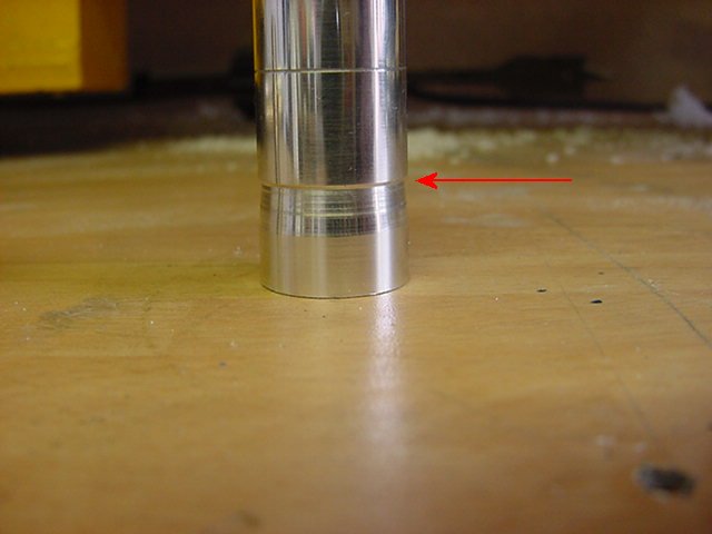
In essence, the larger can was done in exactly the same
method except the inward taper was ten degrees.
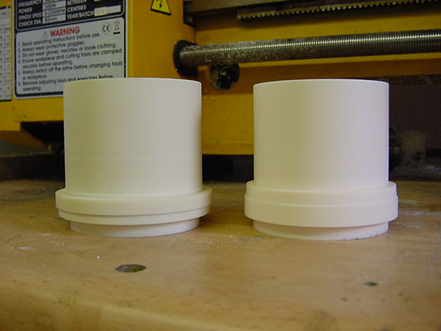
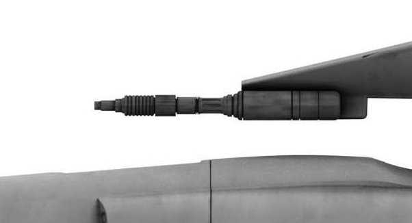
Now just to make sure I was in the right area size wise, the pic below with the engine cans.
Make note of the wide back rings on the large and small cans and how they line up.
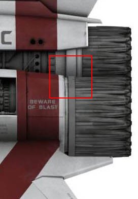
You'll notice that the back ends of the cans line up perfectly in the vertical plane.
So setting up mine like so...
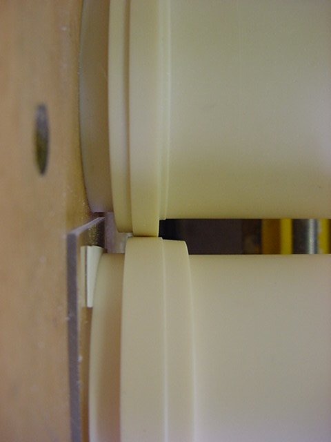
At which point I allowed myself a slight grin, a swift but
sincere thank you to the Lords Of Kobol and a cuppa.
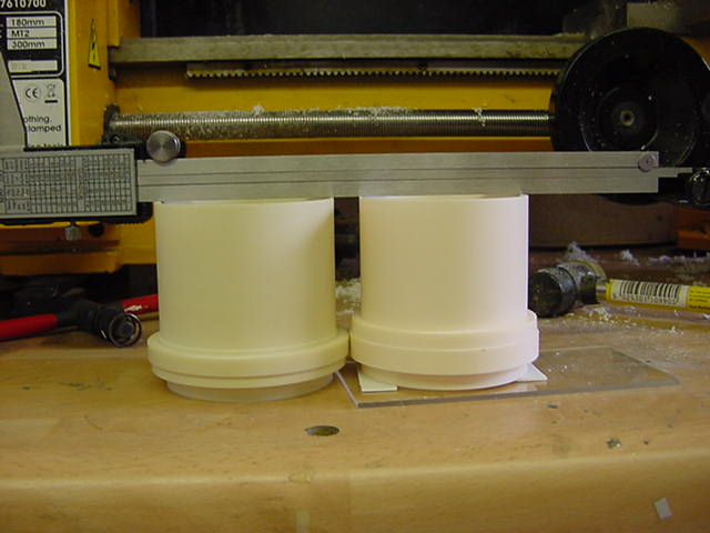
Well that's pretty much the deal with the base engine can masters,
more or less the same details, measuring and roughing out wise,
when it came to turning out the gun masters.
Going from the big picture measurements, I had appropriate metal bar stock to turn those down.
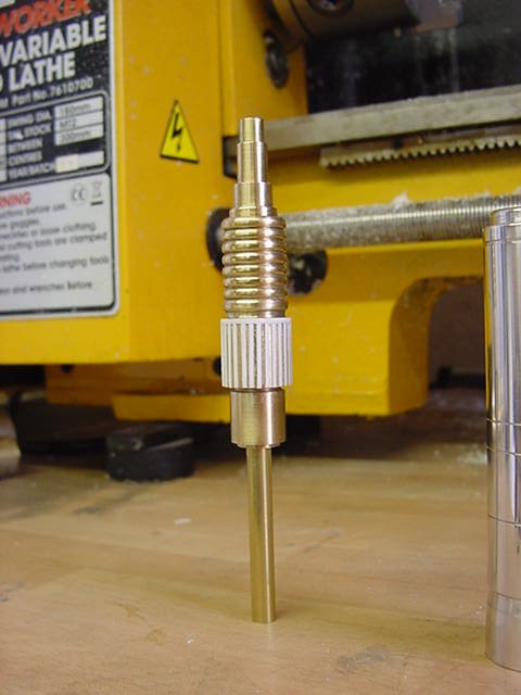
This is the metal in question.
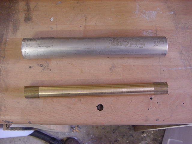
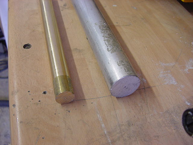
Some 20mm (0.787") brass bar stock and 32mm (1.260") Aluminium.
The brass would do for the barrel and the aluminium for the body.
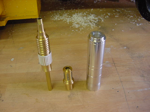
This is the barrel and body in question.
So the aluminium bar was cut to length taking into account of body length
plus enough for about 2mm (0.078") on the front end for facing up.
And approx 30mm (1.181") on the back for holding in the lathe chuck jaws.
Used only the Glanze tools for this and working very slowly and carefully.
Started by turning down the bar to the largest diameter of the gun body from measurements
lifted direct from the drawings and then stepped cut in the two forward rings.
The thin lines were cut in with a fine point tool usually used for screw thread cutting.
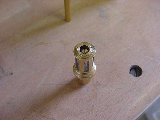
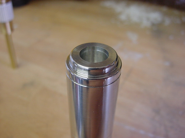
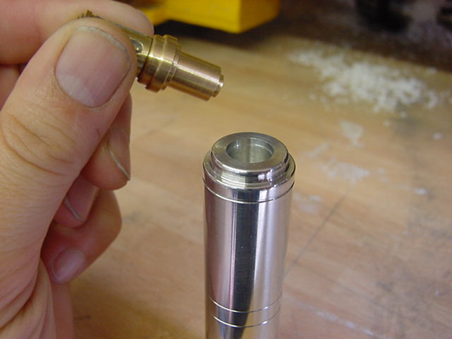
Once done, a 10.10mm (0.397") hole was drilled in the front end.
Done specifically to take the 10mm (0.393") diameter stub that would be cut into the back end of the barrel part.
Overall it looks like this.
The stub at the bottom will form the pouring point for the resin casting.
This will be removed on the lathe when the gun is about to be assembled.
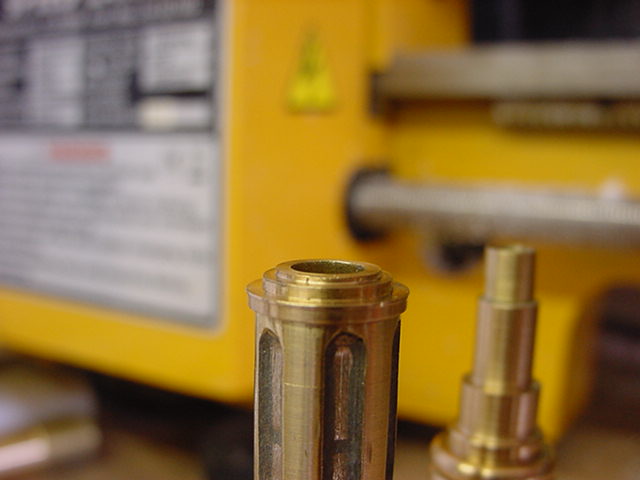
The gun barrel was first turned from the brass bar in one piece, then cut for specific reasons.
One was to mill in the fluted areas on the barrel rear,
the second was that if you look at the gun barrel,
there is a very thin disc between the rear part with the fluting and the forward part.
This part was machined to take a 0.26mm (0.010") thick photo etch
metal disc which will be used when the barrel is assembled.
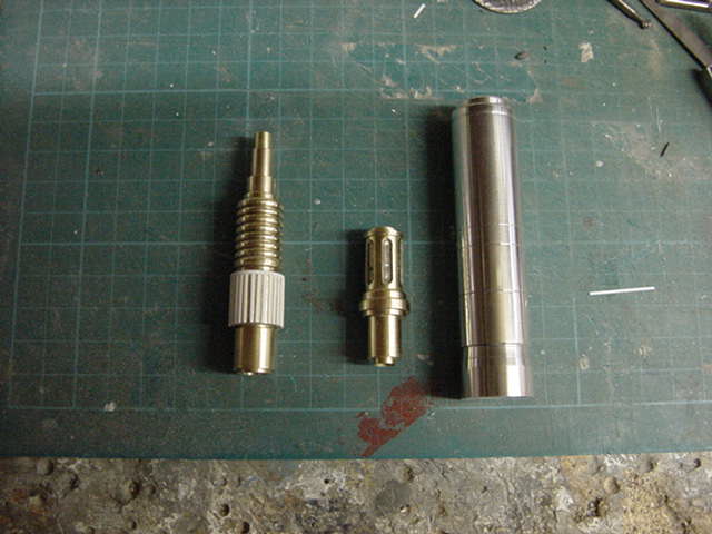
The gun barrel parts were all turned out/milled.
Then some 0.026mm (0.010") styrene strip was glued into place to finish the surface detail.
The parts all looking like this in separate and dry fit assembly.
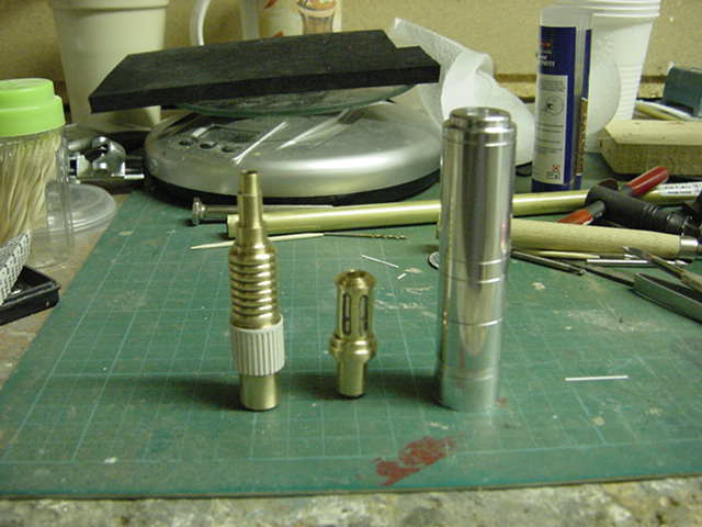
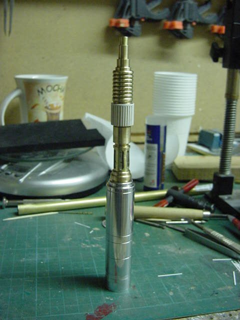
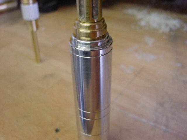
The front barrel part had some brass tube fitted to it and the rear barrel
part had some tube of the next corresponding diameter tube up fitted.
Reason for this is when the gun parts are cast,
some brass tube will be in the mould and when parts are cleaned up,
the front part of the barrel will fit in to the brass sleeve cast in to in the rear part.
Making the completed barrel rigid and lining it up properly without fuss.
Like wise with the stub on the rear of the gun barrel fitting snugly into the body.
And that is that for this round.
Next up is the turkey feather and engine exhaust detail
masters to turn out then some moulds to be made up,
much casting,
more moulds,
silliness ad infinitum.
Ad absurdum and so on.
You lot go easy now, see thee for the next installment!
Page Number