
Battlestar Galactica Viper MkII
1/10th Scale.


 Page Number
Three intersect points to the left...one spline up...hold render...
Now Hit That Polygon Where It Hurts!
Welcome back all!
Been a loooong while but back to this with other things going in the background.
So then, with the arrival of the 3D Printer, what I could really do with
is a mesh of the Viper and a good one from which to make parts.
That's handy...think i'll use that one then!
Now the origin of this is allegedly an original ZOIC mesh.
Not a single clue if that's true but i'm leaning toward that being the case due to how detailed it is.
Seriously so.
I mean and bloody then some.
So the idea being to take this apart and make parts for 3D printing.
At least that's the plan but it's not going to be that easy...
Big surprise there.
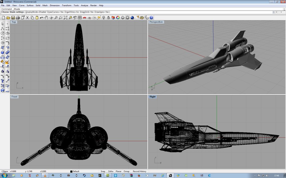
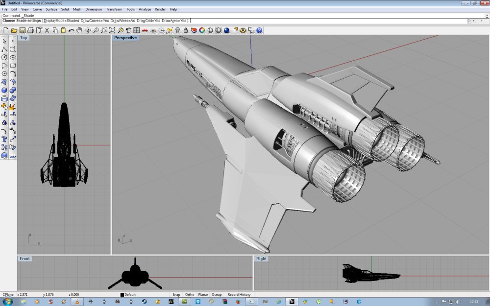
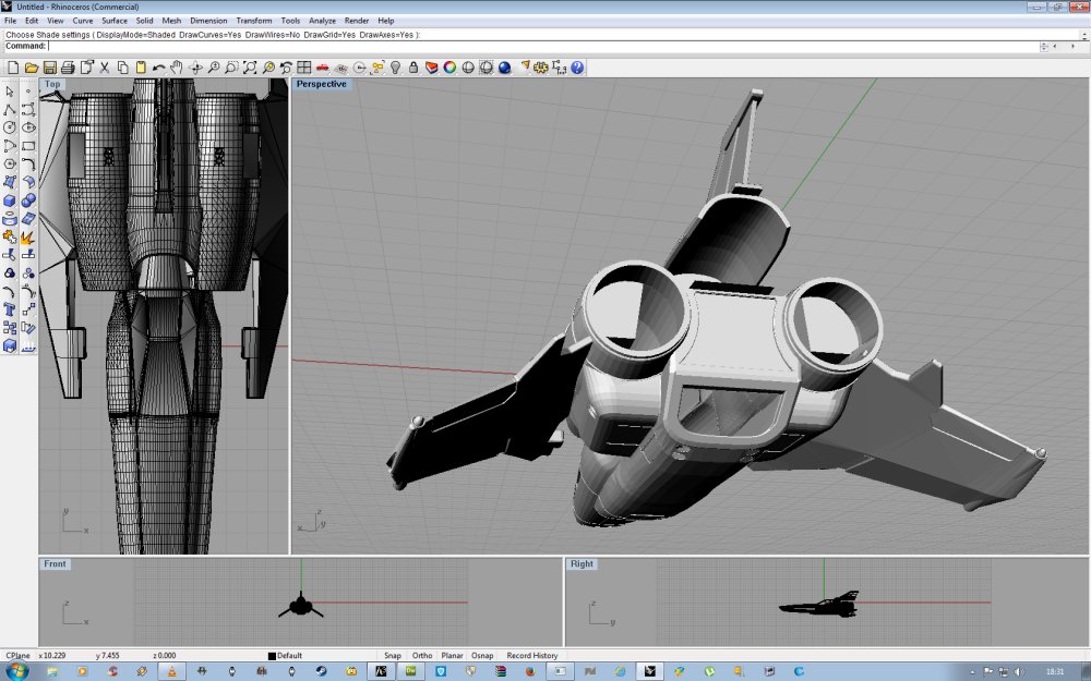
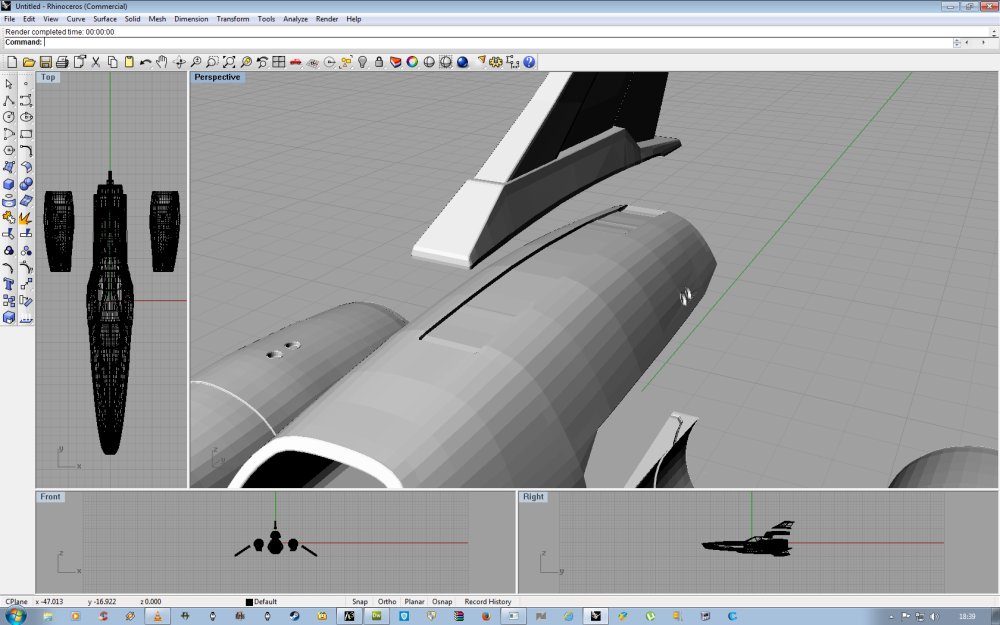
To illustrate, this mesh is for visual work alone, which means it looks great from the outside.
Under the surface however, there the fun starts.
Now stripping away a few of the parts, you can see the internal structure such as it is.
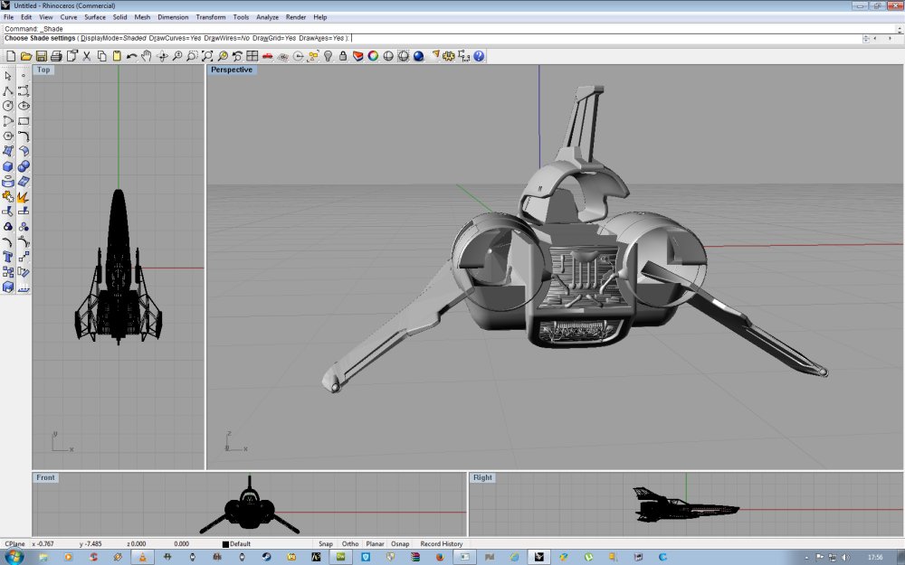
The polygons forming the sides of the rear fuselage, the rear landing gear bulges and the wings
just intersect with and/or overlap all the exterior surfaces.
I've done this myself when I used to make aircraft add-ons for
Microsoft Flight Simulator many moons ago so for visual models, it's no biggie.
For the print pandemonium, it's a different story.
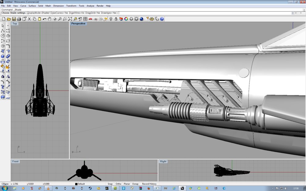
For one example, the main engine pods.
You'll notice there's no fitting inset for the wing root.
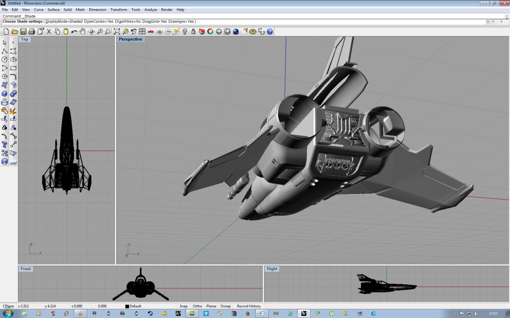
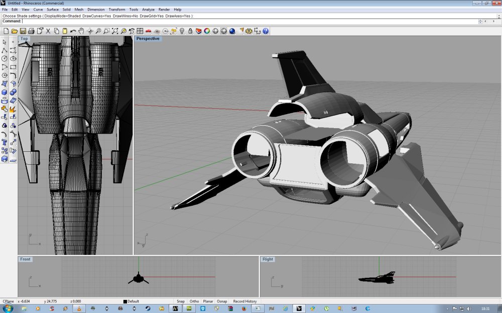
And if you look at the next render, the base of the top fin goes through the high engine shroud.
So the rule is, visual model, excellent!
For parts printing, crap.
By no means the fault of the original mesh artist, I feel sure they didn't have
a grade 'A' nutter like me in mind when it was made so there ya go.
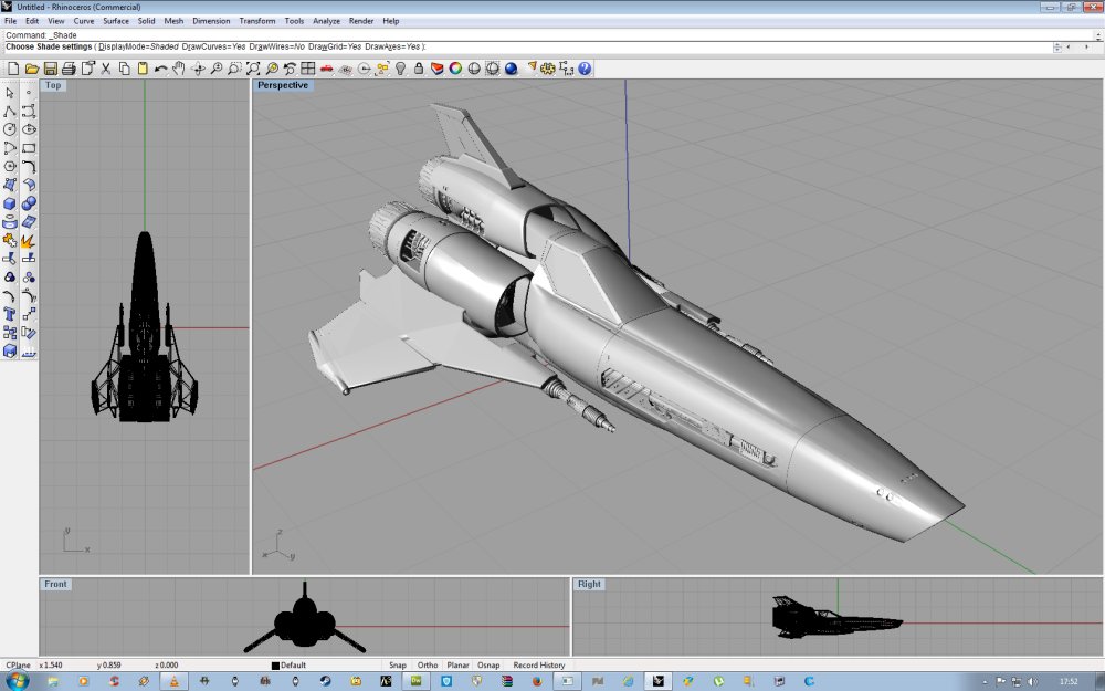
So what we begin with is a lovely render mesh, without cockpit detail but that again is no biggie.
So first things first was to take the main engine housing and rework it a bit.
First to remove all the doubled up on polygons, of which there were a few hundred.
So that took a while...
Remove all the unwanted stuff like the braking thrusters under the flap at the rear.
All lovely details, sadly unwanted here.
Build a new inner skin, thicken said skin.
Add internal shouldering for a new engine detail box, build box.
Make wing root slot and install.
Make all watertight.
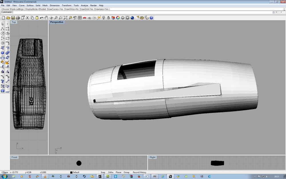
Something like that will do nicely, ta muchly!
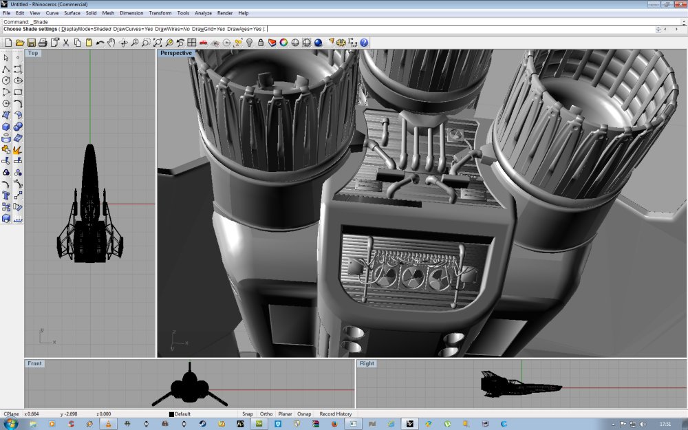
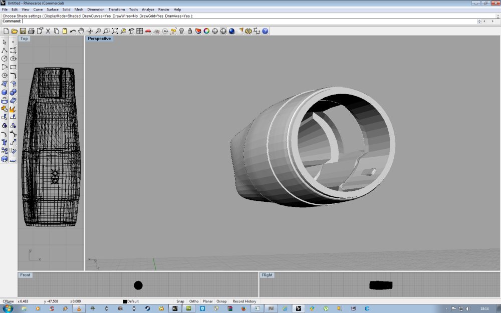
So the next of I don't know exactly how many damn jobs,
was to sort out the main engine pods mounting to the fuselage.
Well the engine pods were joined to the rear gear pods and faired in,
then copies made and the surfaces reworked to make the new rear sides
to the fuselage for physical pieces to fit together.
Sound simple but took nigh an entire weekend to sort out most of it.
And there was much gritting of teeth and squinting at a screen.
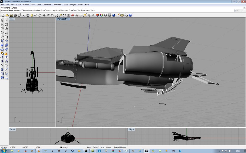
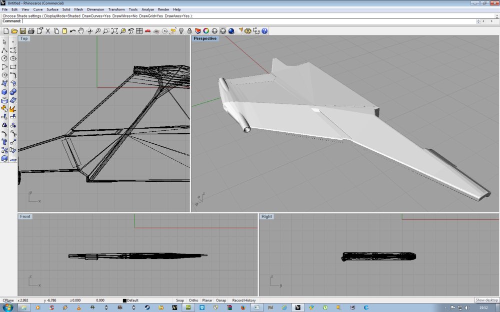
Got it done though, you will recall the original set up, consider this the 'before'...
And here's the 'after'
A bit cleaner with no intrusive poly's where they shouldn't be.
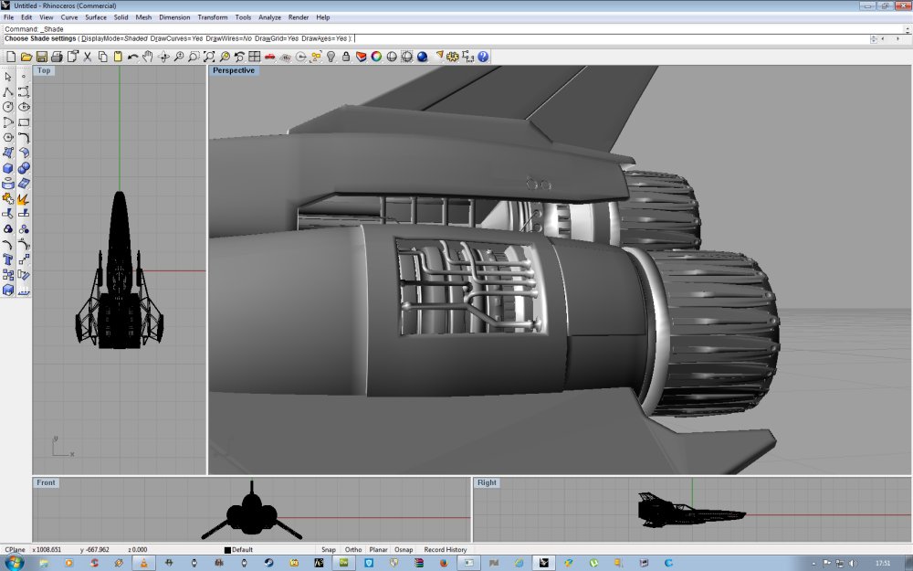
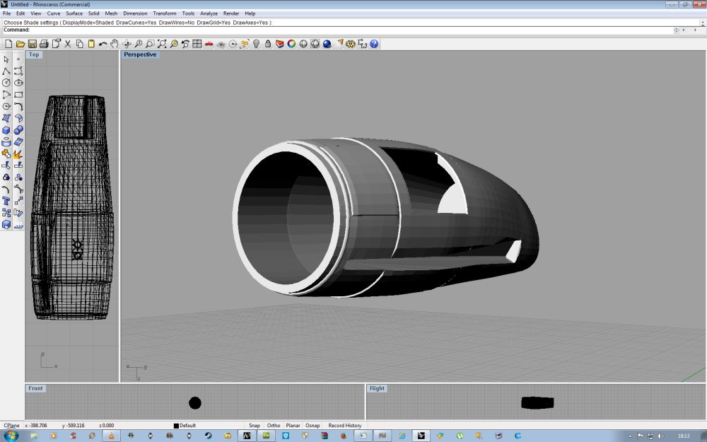
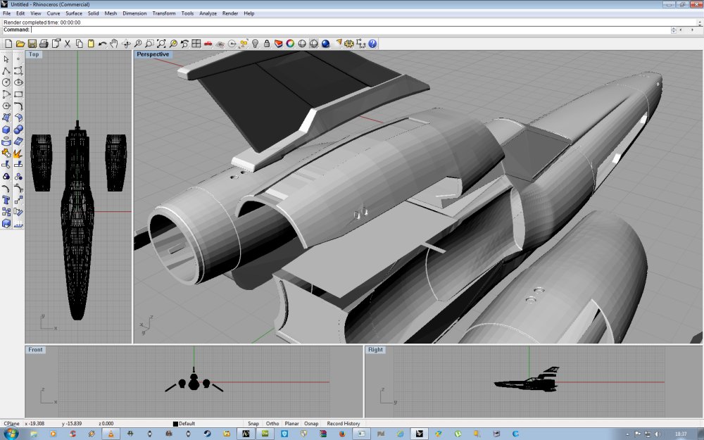
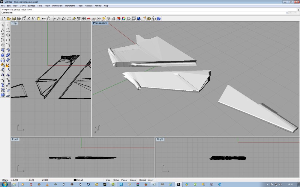
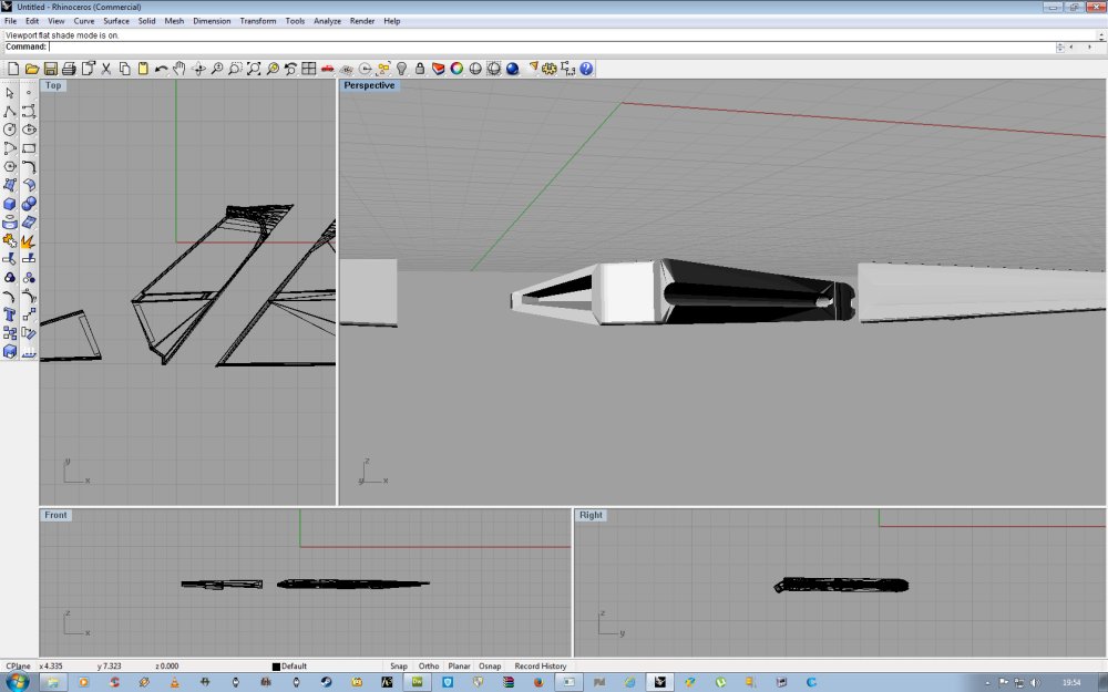
Moving the bits apart for the moment, you can see the revised main engine fitting.
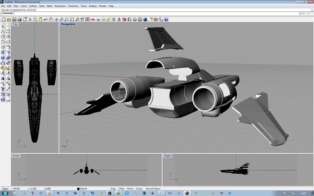
Also the high engine cover/shroud was reworked to make a shallow trench for the top fin.
That also got reworked and made watertight for printing.
The wings got a good looking at and now have wiring holes running from the lights
at the tips to the root for the inevitable lighting lunacy for which I seem to be known.
Not entirely sure whether that's a good or bad thing but there it is.
Wing as one piece...
And split in to three showing the wiring tube built in.
Now the main reason for the split in to three is the size of the print bed on my one.
It's limited to a 200mm cube, that's a little over 7 & 3/4" in old money.
So parts have to fit within that area otherwise the software throws
a right wobbly, takes it's ball, goes home and won't come out to play.
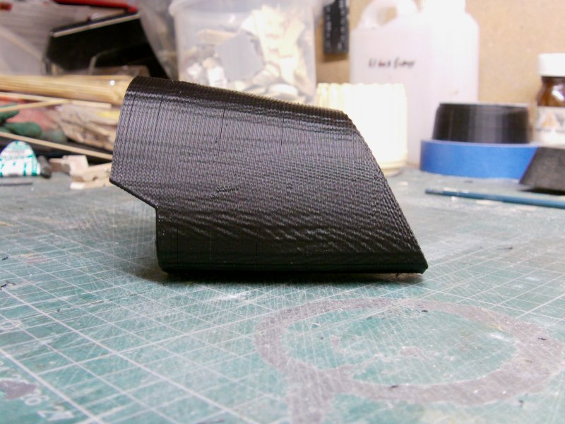
Take for example the high engine shroud...this bit outlined in red...
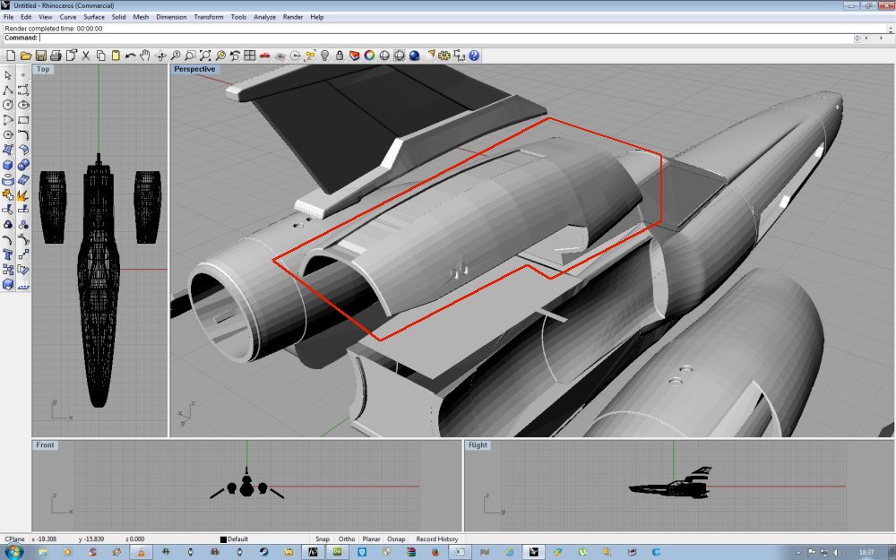
Now in length, this part should measure 242mm or about 9 & 1/2" in length.
So the only option was to split in to two in front and back piece fashion.
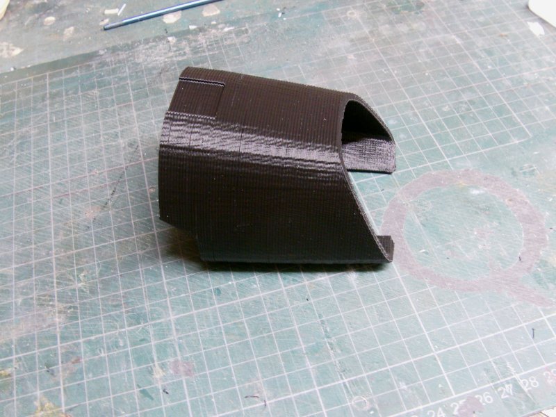
This was done, prepped and the printer got to work.
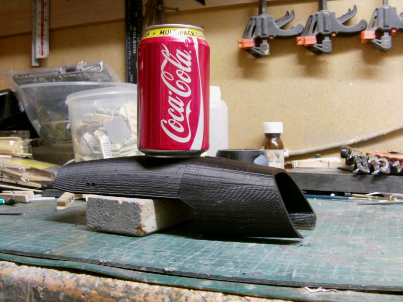
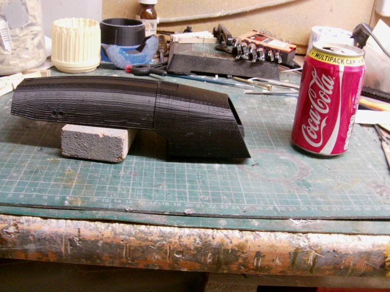
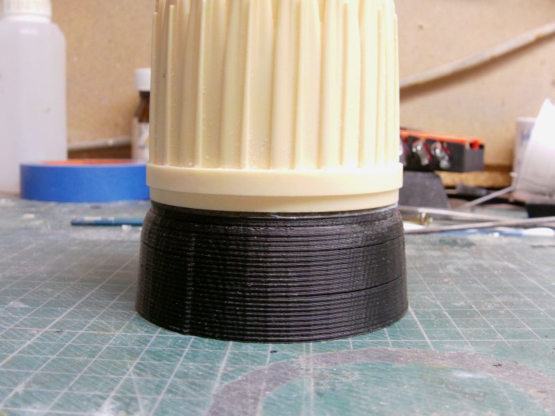
Some 6 hours later and with the support material and base bits removed, we got the front!
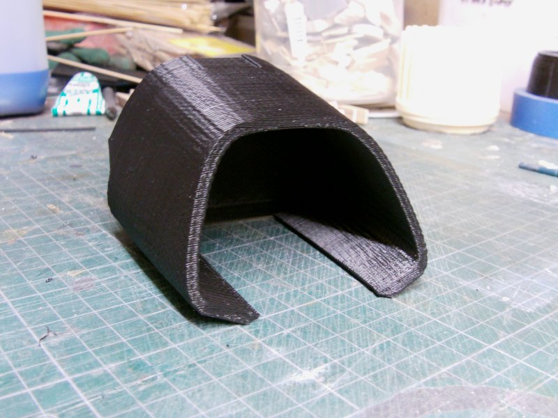
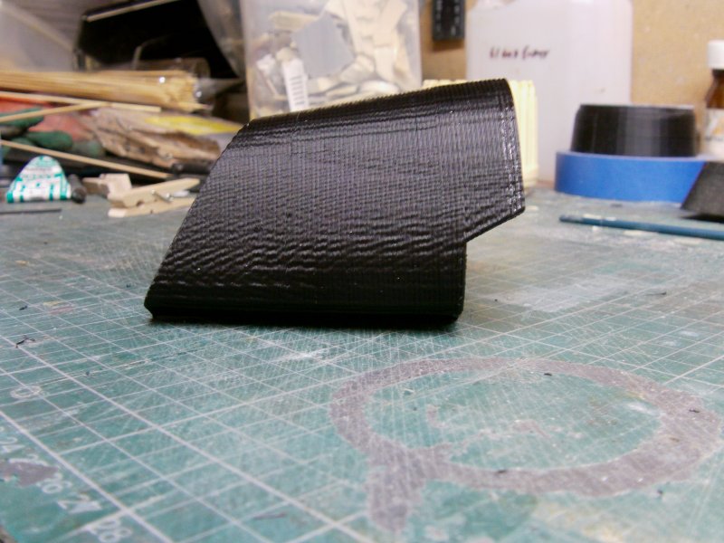
And after a reset and a cuppa, a few hours more gets us the
rear part which was propped up roughly with the front part...
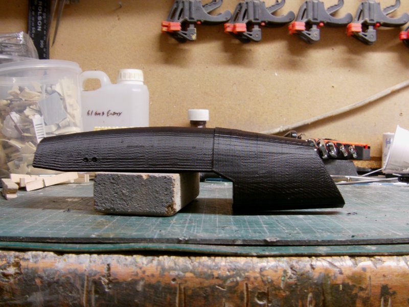
And not forgetting the scaling implement to show size.
AKA the empty coke can!
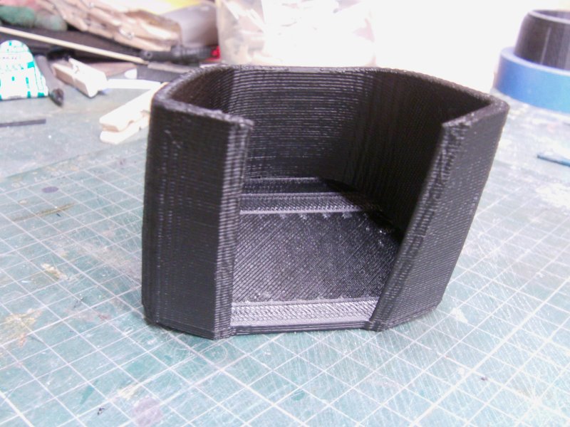
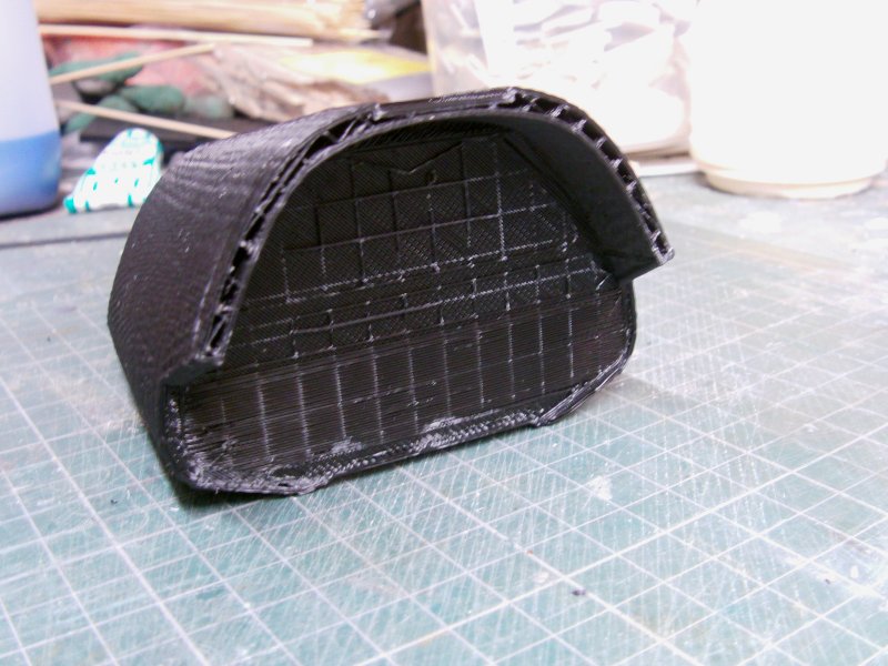
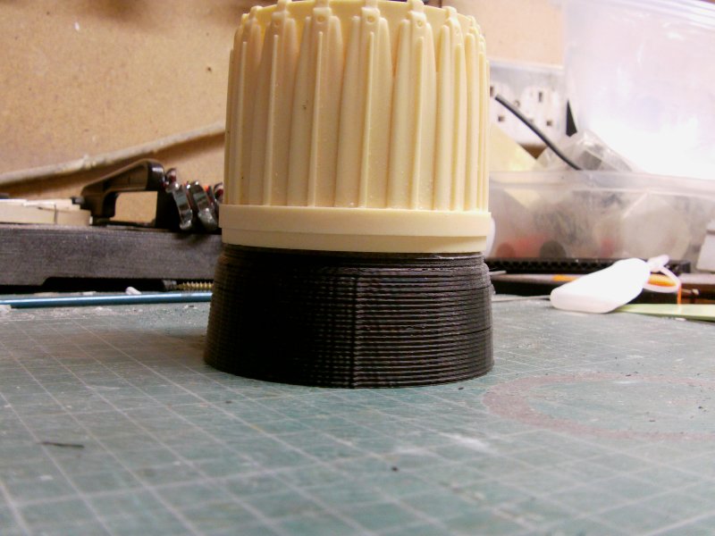
Just to make sure of what i'm getting up to with measurements here,
I did a quick test print of the rear on the main engine pod to see if my resin engine can
I did all that time ago was in the ball park size wise.
Turns out it is...now there's a shock.
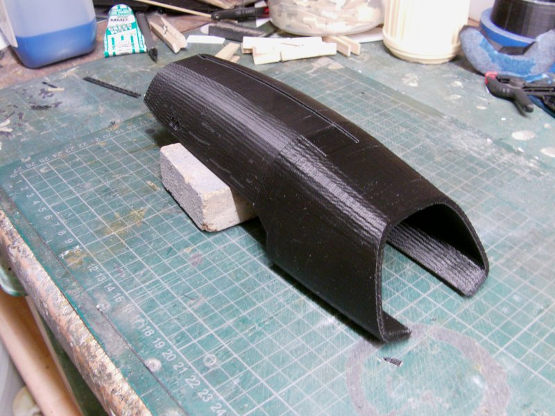
So the bottom line would normally be to join the high engine
shroud parts together, clean them up, smooth everything out
and introduce the part to rubber and resin.
During my fiddling about with test prints in the past, I have found a method
to reinforce the print and make it usable as a part
rather than as a master pattern for casting.
This being the case and if that can be done with this then i'll be building from
printed parts rather than investing in a whole load of rubber for moulds.
Possibly less work true but a large measure of cost saving in materials for moulds and stuff
as I only have three maximum slated to be built by yours truly.
And there will be no more than that as I fully expect by the time I hit said number,
i'll be well and truly sick of the sight of 'em!
Aside from which, while the printer is doing it's thing, that leaves me free to get on with other stuff.
Of which there is a fairly large amount.
That's the lot untill the next update on this long running saga.
You merry mob take care of yaselves and go easy out there now.
Page Number