
Sovereign Replicas USS Enterprise NCC 1701-E
1/650th Scale


 Page Number
Back again with just a few small things to take care of...
Wedging The Wiring Into Place
Right then, a bit of waffle first up
After much hoo-ha and faffin' about the nacelles were assembled and prepared to be glued to the pylons.
This is where a problem came along.
I had decided to do the same as with the refit,
that is to say wiring for the flasher/strobes etc and main lighting
be kept separate for battery and mains respectively.
And that was when the problem came up.
For the battery stuff I usually use 7/0.2 hook up wire,
a decent general purpose wire and 16/0.2 for the mains since the wires
handle 1.4 and 3 amps top end respectively.
I've tried the bussard effect units at low milliamps and over about 300Mah and at 12 volts
they simply refused to function, i.e. they just stayed on with no rippling effect.
Since I really did not want to fiddle about with hooking up mains converted power and running the whole
shebang off one feed and risk blowing electronics I could not replace,
I had to split the wiring into 4 separate feeds.
One for the blue LED strip, one for the rather cool bussard effect modules,
one for the strobes on the back of the nacelle and one for the
light at the very top of the nacelle.
Turns out I should really have checked the internal sizes of the brass section cast into the
pylons and despite my best efforts it wasn't all going to fit down there with the two wire
types so a quick rethink and a few calculations,
a good head scratch and a quietly said "frack it" later all the wires are now standard as 7/0.2 wiring.
So onto the rest of the deal, having a quick count up and placing my limit for main lighting power
at 12v/1.3amp I came to the concluding amount of 65 LED's for main lighting.
In short even with that amount, it's doable...
I hope...
shall we?
Nacelles assembled and pylons glued on.
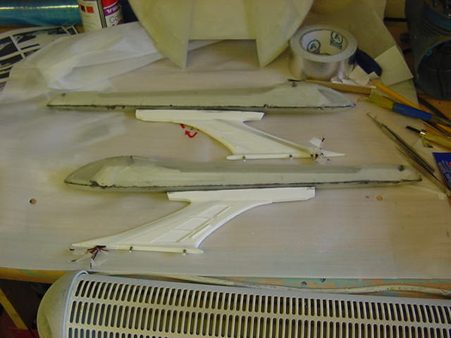
Spotlight Silly Stuff
Now one thing that does spring to mind here is that there are two spotlights on this beastie,
both on the front top and bottom respectively so here we go
First up was some drilling and grinding vandalism.
Then the insertion of two 3mm white LED's with a smattering of filler and some deft filing work,
not the finished article by a long chalk chalk but...
That done, onto the next bit and now for some words you'll only hear me
use once in all the larking about i'm doing with this kit...
That Bit Is Inaccurate, I'd Better Fix It
Yeah I know I said this kit is bloody accurate and by and large,
I stand by it but i'll hold my hand up and say I didn't really notice
it untill reviewing my copy of Star Trek Nemesis again for some lighting details
and it suddenly occurred to me that something was not quite right.
Now before we got into this, I don't know if it's the same on all the kits or if SR has
changed the part to match the one on screen in later issues but here it is anyways...
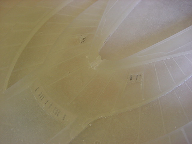
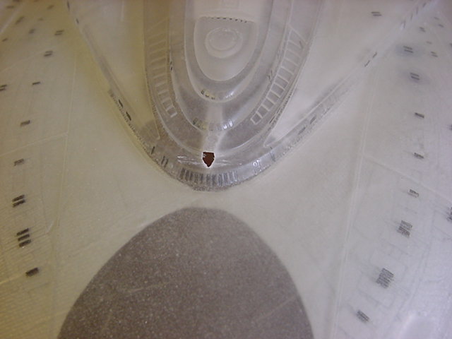
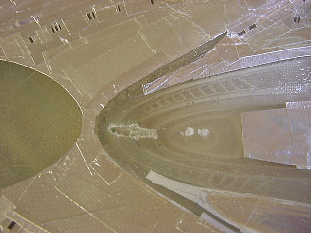
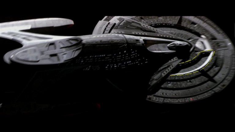
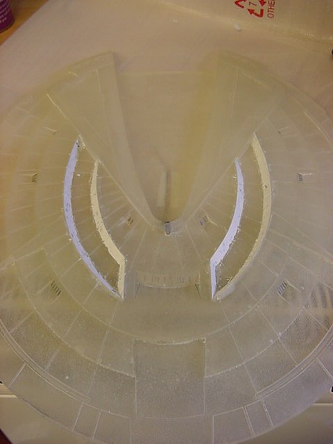
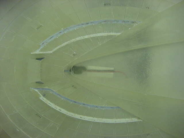
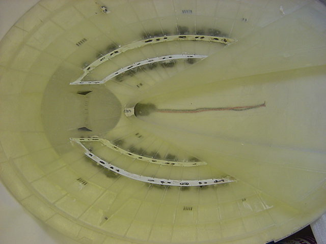
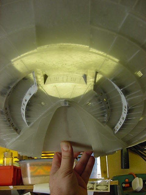
The screen caps and one pic of the effects model with the area
in question arrowed and lined for your viewing.
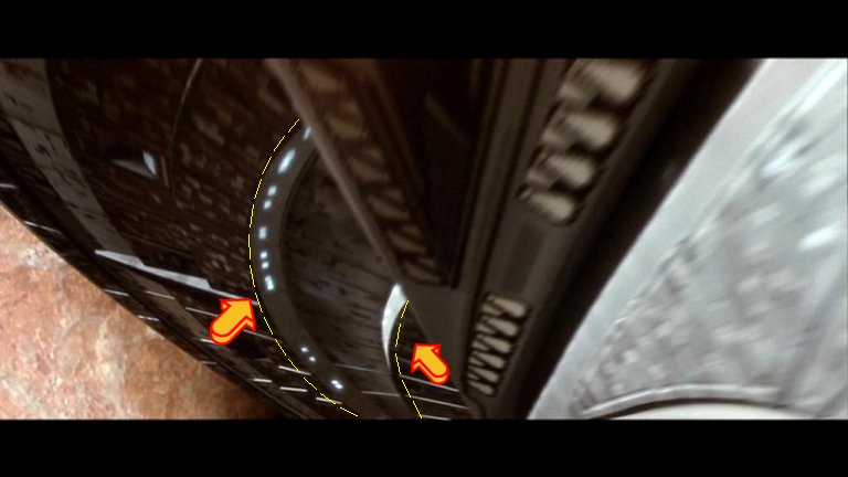
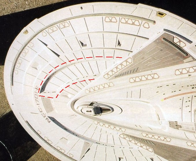
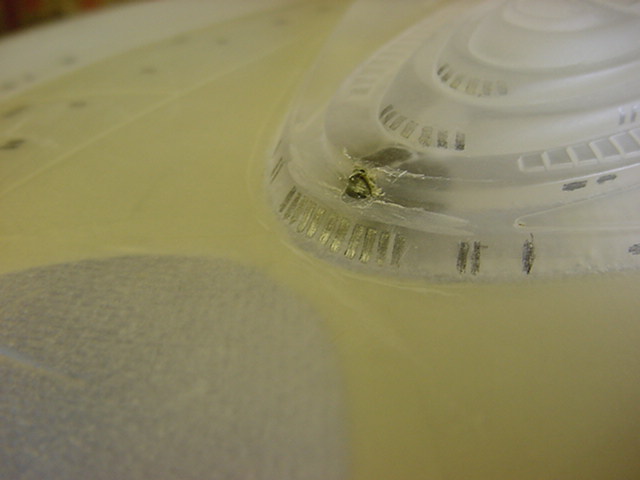
Now from what I can see, the walls of the 'trench' are slanted,
on the kit however,
they are most certainly not.
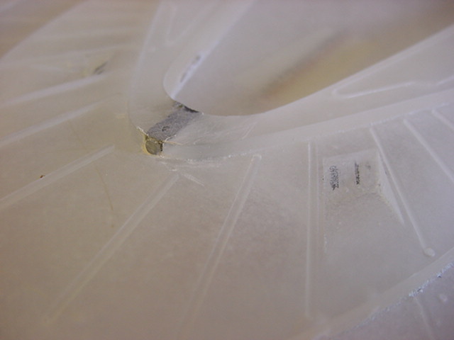
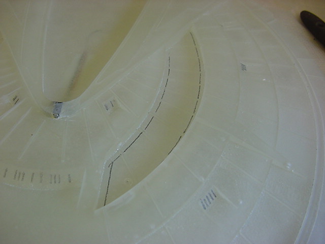
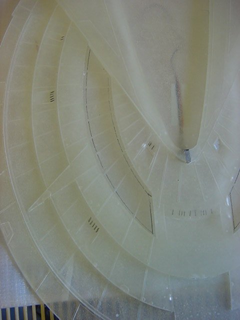
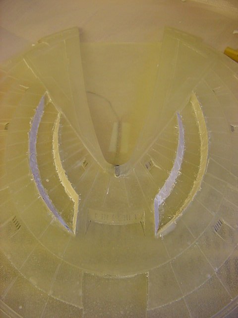
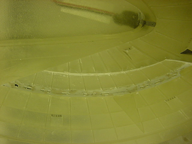
Here is said part with some pencil lines drawn in by yours truly to show
approximate slant of where the walls of the trench should angle to.
Now one could ask the question, how big a deal is this?
Well the only answer I can give is "no biggie" and no i'm not kidding either.
Over a coffee...
large, pint of, thinking deeply for the use of...
and a smoke, I decided that the tube of epoxy putty I had laying around was about to
justify the whole �3.99 I had spent on it.
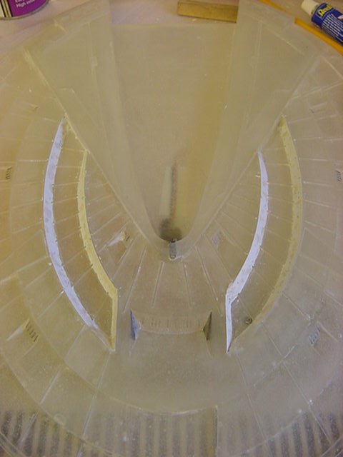
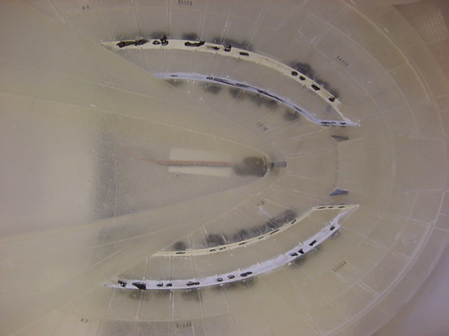
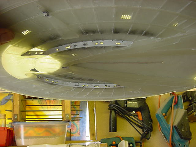
So first up, light sand and cleaning to the the surfaces,
mix up a fair wedge and liberally plaster about said area
with best tools available, namely fingers and thumbs...
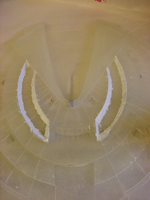
A quick chisel assisted removal of most of the overspill...
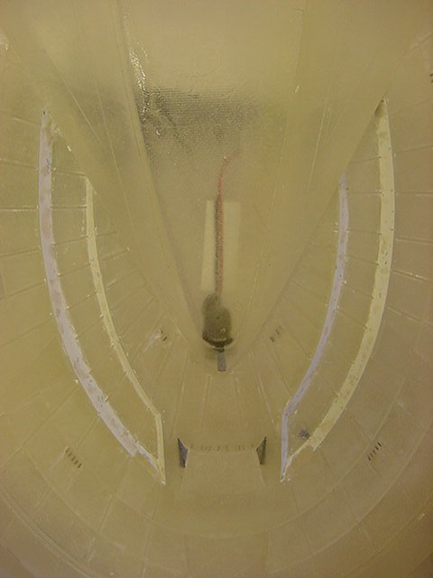
Followed by a scraping of fine putty and a good sanding down to smooth off...
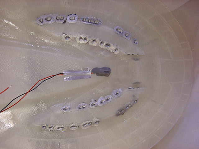
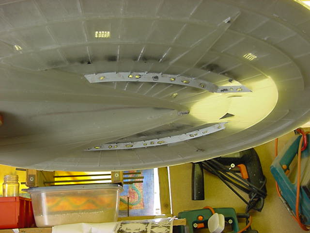
Final job to do some digging and application of putty and the like to also slant
in the side walls of the forward window areas as is correct and lastly a dollop or two of
clear epoxy in certain areas.
The reason for all that hooha and why some parts are filled with clear will become apparent I assure you
but not in this update so your just gonna have to wait.
Ok then all that lark a done deal in a few hours, don't ya just love fast curing epoxy ?
On to putting the windows back in.
Now, since paintwork and so on will take more than adequate care of the final window shape,
accuracy in drilling and so on is not really a prime concern,
first to mark out rough window positions.
And then drill and grind the living daylights out of said marked areas.
Then go in hard with the matt black and overcoat with silver.
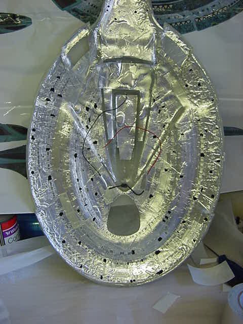
Then it was time for the foil treatment.
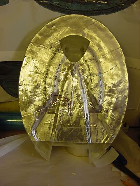
Some of the windows were filled with clear resin and some plugged so we got lit and darkened windows.
Lastly an exterior cleanup and that was pretty much that for this bit.
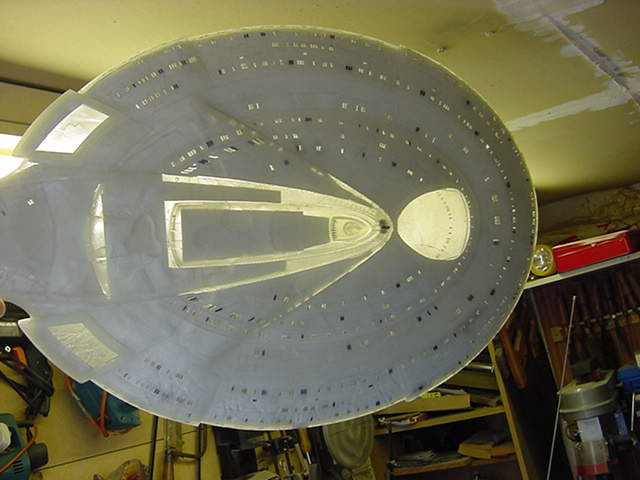
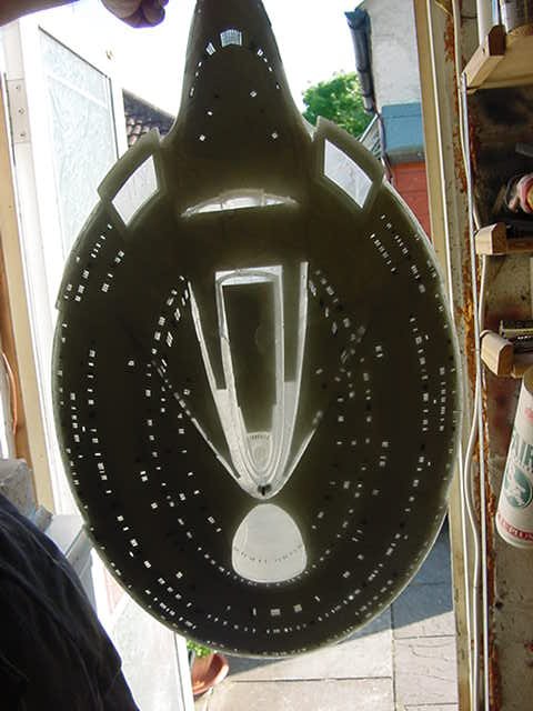
Last bit for this update was a potter about the top of the saucer and start blacking in some windows,
just for a bit of lighting variation.
A decent dab of matt black on the inside.
Each bit then foiled over and that will about take care of this.
That's your little lot for now my friends,
i'll be tinkering about some more with the beastie as we now closing in on lighting installation proper...
that will be fun will it not...sorta.
Take care you lot and above all and as usual, go easy!
Page Number